One of the common themes of this whole boat restoration has been the family reminding me of the pensioner who hit national newspaper headlines and the evening TV news a few years ago having spent years restoring an “old” boat only to sink within an hour or so of the launch. As you might expect they dont listen to my replies that you have to expect that for dried out carvel or clinker planked wooden boats because the wood needs to swell up to get fully watertight. They also dont listen to “it is fiberglass so my boat wont leak like that”. I think they have visions of me involved in a scene like the opening of the first Pirates of the Caribbean film.
I am confident it will be ok as the hull has worked more like a water butt during the restoration with the challenge being to get the occasional rain ingress back out of the boat. However it is more like a dinghy than an ocean liner so I do have to be prepared for some water to get in if (or when) I get waves coming aboard. A reasonable amount of bilge pumping capacity makes sense especially as the starboard locker more closely resembles a shelf rather than a watertight compartment. Towards the stern the engine exhaust system comes up through the bottom and almost up to deck level to keep water out of the engine. There are also two ventilation inlets in the cockpit sides leading to the cabin and engine compartment so the top half of a swamped cockpit will empty rapidly into the boat rather than out of the drains in the transom.
Rathenice arrived with a hand operated bilge pump located in the starboard cockpit locker connected to a hose that reaches almost to the engine but obviously nowhere near to the lowest point of the hull. There was no provision to empty the forward locker under the V berth so I had to bale it out on day 2 after all the jet washer water got in through the chain locker so I knew early on that I needed 2 pumps. A third effective water tight compartment became obvious when rain water got in through the window openings while the glazing was being re-fitted. This includes the large locker and underfloor space at the cabin table and is connected to the storage space under the galley as well as the ventilation inlet near the floor.
As it made sense to run the outlet pipe from the engine compartment to a point beside the outlet for the manual pump that needed to be sorted out before the engine went back in. Bilge pumps can have one way valves but are often reckoned to be safer if they rely on the plumbing path to prevent water siphoning into the boat so I intended to take each of the pipes as high up as I could on their way overboard.
I had originally intended to have just the three electrical bilge pumps each with a float switch but the design ideas evolved a bit especially after I got the pump working in the engine bay in December 2019 and started to look into non return valves because of the volume of water that came back down the pipe when the pump stopped.
Sunday 29/10/2017 I have been thinking about the bilge pump plumbing as the hose is due to arrive tomorrow. At least with the plan outlined below I only need to install the stern compartment’s pump plumbing before the engine goes back in.
- Bow area pump is obviously going to be in the locker under the V berths as the rest of the fore cabin is linked to the main one. I think the pipe should go up to the cabin roof then do a 270 degree vertical loop to keep out any spray or solid waves that get that high and then go out through the side of the cabin onto the side deck. That will minimise the pipe run without putting a hole in the hull at an area which might go under the water if sailing with a serious heel. If there is sufficient flat cabin side it is probably best to do that on the port side of the boat as the pipe loop can be mounted against the toilet bulkhead.
- Midships pump might be practically placed in the galley storage under the cooker with a similar 270 degree turn located inside the hanging locker. Again high enough outlet to be always above water but minimal pipe run. Will need to install scuppers to let any water from the cabin floor into the bottom of the locker and possibly closable ones in the under bed locker and from the heads compartment into the cabin. I don’t want water getting in the battery locker and the main under bed locker if it is in the cabin or engine spaces but may need to be able to empty those spaces if necessary. Maybe need a fourth low capacity pump which can plug into the cigarette lighter socket when needed.
- Stern (engine) compartment pump can be alongside the engine close to the removable engine partition. This one will have a longer pipe run to an outlet as high as possible in the transom or alongside the manual bilge pump discharge. As this run does not go through the cabin space there cannot be as high a loop to keep out backflow but that shouldn’t be a problem unless there is a serious swamping from waves coming from aft in which case waves breaking into the cockpit is a much bigger risk than the bilge pump discharge. That risk is not helped by having two air inlets at about half the cockpit depth which go directly into the engine space and the cabin. Might need to do something to be able to block those vents properly if needed in an emergency.
- Float switches for the three individual pumps will be close to the pump itself as close as possible to the bottom of the compartment. The fourth high level switch will be in the engine compartment positioned above the bottom of the engine opening so it triggers all of the pumps if there is likely to be water getting over the top of that partial bulkhead.
Wednesday 8/11/2017 After another re-think, the engine compartment bilge pump tube was installed through the space above the single berth and the starboard locker through to a skin fitting just forward of the manual pump  outlet. Still needs holes to route it into the engine compartment and I need to apply the sealant to the outlet fitting at the same time that it gets done on the hatch cover. I should also apply some sealant around the hole in the bulkhead so there is no possibility of water
  getting into the cabin via the starboard cockpit locker. This is the highest point in the pump flow route and is just under the moulding of the cockpit coaming. The skin fitting is about 30“ above the waterline and then there is about a 6” uphill flow to the highest
  point and therefore fairly little chance of siphoning water into the engine compartment due to heeling.
Saturday 11/11/17 Woke slightly before the alarm so got a good start and was at the boat by just after 8:00.
By the time Matthew phoned me just after 10:00 I had put sealant around the bilge pump outlet, installed the lower rudder hinge, waterproofed the soldered joints on the engine stop switch, done a temporary install of the engine control box with M6 threaded rod and put sealant around the cables where they enter the locker. Not a bad bit of progress especially when the rudder hinge installation requires crawling head first under the cockpit floor to put on the washers and nuts and tighten everything up.
That gives you quite a good impression of a fairly typical couple of hours at the boat with bits of several different tasks going on together. To put even more of these single subject posts in sequence, this was the same time that I was starting to re-assemble the engine exhaust system on the workbench at home. I was also knocking out walls in Matthew’s newly acquired house – The rest of the work on that meant very little progress on the bilge pumping for almost a year.
Saturday 25/11/2017 Centre section of the cabin seems to be slowly filling with water. You can now hear it sloshing slightly when walking on the inner floor around the galley area. About an inch deep when you put a hand through the vent below the table. Not sure whether this means there is a leak letting in rainwater or it is condensation as a result of the cold weather. Will have to start doing something about a bilge pump.
Tuesday 1/2/2018 Happy Birthday Grace!!!
Got access to a lot of information about bilge pumps and the capacity needed for particular leakage rates. All of it points to the same sort of problem in that you need much more capacity to deal with any real problem than the ordinary electrical pumps provide. However I do seem to be going the right way with having moderate capacity in each of my three distinct partitions. Sites like www.safety-marine.co.uk reckon efficiency losses mean most pumps will deliver less than 50% of the advertised output in a real situation. Combine their figure that a 2” hole three feet below the waterline will let in 20,000 L per hour (5,500 gallons per Hr) with a typical electric pump capacity of 500 Gals per hour and it is obviously just a gesture. I am going for three such pumps so might cope for a while with a 1” hole nearer the waterline. Definite message though that engine driven pumps are better, it is essential that the batteries and bilge pump electrics can operate submerged and also that significant manual capacity will also be needed if anything moderately sized should spring a leak. In short the message is to turn off any through hull plumbing that is not in use, have the equipment and a plan ready to fix holes but above all not to run into anything. Bilge pumps can help gain time but are really only any use for the more minor issue of water splashing aboard and slow leaks.
Friday 21st December 2018 Matt had visitors so nothing done on the house. I went to the boat instead to check on the rain ingress problems. Some water in the engine bay again but not enough yet to reach the engine. Cockpit doesn’t have any water in it so I am not sure how the water is getting into the engine bay. Does suggest that I need to get the bilge pump installed fairly soon so I can avoid getting the engine wet if I cannot get to the boat for a week or so anytime.
Saturday I have been looking at how I could monitor bilge pump operation and battery state while away from the boat. Ages ago I saw something about this on a boat restoration website, they were suggesting using an SMS messaging module intended for burglar/fire alarm systems. Typically these monitor relay contacts but obviously float switches are very similar. There are a few options –
A – Simple relay sensing systems
- Honeywell ADE alarm dialler(£79.00 )
- A5 GSM auto dialler – This is the one suggested on the website. (£69 via ebay or £74 from Advent controls) Has 2 digital sensor channels (eg an entry alarm & pump activation) and could activate one remote controlled function.
B – Relay and battery voltage so can remotely check battery life, be alerted when power is failing and recharge as needed.
- D4 GSM auto dialler – (£84 from advent controls) 4 digital inputs & 2 analogue inputs plus on-board power supply voltage monitoring. pdf
C – Relay, supply voltage and other parameters
- RTU5023 GSM alarm (ebay from china – £57.99 with sensors & antenna / £45.88 without the antenna extension & sensor ) Digital sensors but also temp, humidity (with the sensor kit) & supply voltage
Any of these would be able to dial a mobile number and alert that there is a problem either with water ingress or battery reserve.
Saturday 28th September 2019 Cut the hole to get the bilge pump outlet pipe through into the engine compartment. Ordered two of the pumps so that should be almost the final bit of work in that area (That order fell through for some reason – out of stock I think).
Sunday 24/11/2019 Today I ordered the first of the larger capacity bilge pumps. Should arrive in time to be able to install next weekend.
Tuesday 26th Nov No particular rush to install the bilge pump as the float switch is not on the way yet however I can start making the boards to which the pumps will be mounted. Mainly a painting job to avoid the plywood de-laminating when semi permanently immersed in water but will still take time.
Ordered the other two bilge pumps, the tank fitting for the fuel pipe and also the tricolour & anchor light that will go at the top of the mast. Will be making plenty of progress shortly as the other electrical bits are due to arrive tomorrow.
Went to the boat at about 7:15. Unloaded all of the new parcels that will need installing there and spent some time temporarily fitting the bilge pump in the engine compartment. It fits rather conveniently between the cooling inlet seacock and the fuel filter and will be well out of the way of the flywheel and any pull starting attempts. Attaching it to a 6” square plywood piece will keep it there and provide somewhere to mount the float switch as well.
Friday 6/12/2019 Now have the four float switches for the bilge pumps so part of the tasks for tomorrow will be to cut out at least one of the plywood mounts and start the protection process to stop the cheap ply from falling apart, covering it all over with resin will make a good start then a coat of paint.
Saturday 7/12/2019 Woke up well before my alarm and even early for the weekday timing. Was dressed and finishing my breakfast before the alarm went off. Arrived at the boat around 20 past 7 while it was still fairly dark.
Installed the proper bilge pump wiring so the one in the engine bay  now works off the “always on” switching in the port side control box. Doesn’t have the float switch controlling it yet because I left the mounting plate behind last time. No more water in the bilge than when I was there last so not enough for the pump to actually dump it overboard but there is enough to show the pump works and confirm that I will need a one way valve in the pipe as the water flows back to give over an inch sloshing around near the electrics and engine.
This time I remembered to bring the bilge pump mounting assembly  home to do the resin coating and painting.
Thursday 26th December 2019 Awake and having breakfast by 7:30.
Next job is waterproofing the two bilge pump attachment boards with resin. Started that one by warming up the resin by taking the tin into the kitchen while I organise myself some lunch. It was nicely warmed  after I had collected Helen and was starting to thicken by the time I had mixed in the catalyst and painted the edges & both sides of the two 6” squares of plywood.
Thursday 2/1/2020 The only boat work tonight was a decision to follow the advice on some of the forum sites which advise against having one way valves in bilge pump outlet pipes. The suggested solution to back flow from the outlet pipes is to have two pumps – The high capacity one is expected to clear large amounts of water in the event of a swamping or major hole and one or more smaller “bilge drier” pumps that will deal with smaller amounts of water including the backflow from the main centrifugal pump when it is shut off by the float switch. The pumps I ordered are capable of 4 l/Min and max pressure around 100 PSI so more than able to provide water to taps in horseboxes if we dont use them in the boat. – I got 4 of them so we can experiment.
Saturday 4/1/2020 Up at 7 because Matt wanted me at his house “first thing”.
Also received the four additional pumps while I was at Matt’s house. Need some 10mm bore plastic hose but will then be able to empty the hull completely and hopefully reduce the amount of condensation happening every time the weather gets a little wet or colder. They only do 4L a minute so capable of dealing with a moderate leak but not a full blown swamping or broken pipe of some sort.
I bought 4 diaphragm pumps (https://www.ebay.co.uk/itm/100PSI-4L-Min-High-Pressure-Diaphragm-Water-Pump-For-RV-Caravan-Boat-Garden/223767680617?_trkparms=aid%3D555018%26algo%3DPL.SIM%26ao%3D1%26asc%3D40733%26meid%3Df7d4f3e80be347729d68205dcf7867e5%26pid%3D100005%26rk%3D1%26rkt%3D12%26mehot%3Dpf%26sd%3D254329376578%26itm%3D223767680617%26pmt%3D1%26noa%3D0%26pg%3D2047675&_trksid=p2047675.c100005.m1851 ) so there will be one in the engine bay, one will be dealing with water under the cabin floor, one for the front lockers under the V berth and one for the heads compartment. Not sure where I am locating them all because the motors need to be away from the water but at least 2 of them can easily pump their waste water into the cockpit via the engine compartment air intake. I am going to need to do some experimenting with electronic switching and water collecting arrangements to make the pumps work effectively because I don’t want them running dry for too long or picking up too much junk because the valves are only flaps in the diaphragm which may stick open rather easily if too big a particle gets into the system. Blocked pipes shouldn’t be a problem because there is a pressure shutoff switch and also an over pressure bypass valve to let water circulate if the pump says on when there is no flow.
Sunday 12/1/2020 I have been researching bits for the bilge pump project for the last few days so here is a summary of the sub section of the bilge pump project –
I will try to explain this for those readers who are not part of the current “maker” culture and weren’t part of the 1980’s home built computer revolution that preceded the mass use of computers for work and gaming (most of the latter group are probably already at home as ‘makers’ because that was basically what you had to do to get your computer working). Feel free to skip forward if you dont want to know about the hardware but you might learn some useful ideas to build other projects so at least consider skip reading.
I am really a bit of a computer nerd so I can seriously expect to be able to take a modern microcomputer board and some electronic components to create a multi channel system which senses water levels and makes decisions whether to run the corresponding pump to empty the area. Way back when I was teaching myself the internal ‘machine code’ language of the 6502 chip that ran the Acorn Atom, BBC micro & other computers, I had to do that using chips, transistors, relays and other components. As well as building and using these types of computer at home, I did enough of that as part of my research job to regard this project as fairly easy. Actually it is a lot easier to build a prototype device now because of the existence of single board computers and a selection of add-on boards that do useful things like switching high currents using the output of the computer chip. The computers range from microcontrollers with relatively little computing power (although still probably more than the most basic early home computers) up to single small boards which are far more capable than an average PC.
Possibly the best part of the current culture is “open source” program availability where people publish projects on line so others can help improve them and/or learn by copying them either in their entirety or just take the sections of hardware and computer code that you need for your project. Projects (or sketches as the Arduino programs are called) can be as simple as flashing an LED or as complicated as an autonomous satnav enabled boat, car, drone or aeroplane. And yes you can find boat related open source projects like home build self steering systems of varying sophistication!
The idea is to use an Arduino which is a single board micro computer using a chip designed for car electronics. This has a lot of capabilities because of built in analogue (ie voltage measuring and output) devices, timers and other hardware which would previously have required wiring up and programming an additional chip for each function. The chip has re-programmable memory which will retain it’s program when switched off and also has the ability to go into a power down mode when it will use very little power until woken up by a timer or an external signal. The really clever thing about the Arduino and similar boards is that permanent on chip programming means you can just plug them into an ordinary PC via the USB cable to install a new user generated program in a few seconds. Fixing a problem in the high level human readable language can take only a few minutes rather than the 1980s version of software development where it could take a couple of days to re write assembler code, erase memory chips and re-program them or even having to replace the entire chip if it had a non erasable program memory. The connected computer also works as a display screen so you can graph results or print to it while developing your sketch. About the only down side is that I have to learn a new language which is rather like C++ but the open source sketches and libraries of functions to operate particular chips make that fairly easy.
So the final aim is going to be approached step by step but will be close to this –
Chip runs a routine to power up the sensors, check them all then set the timer and power down again if OK. If anything is sensing liquid then the software can run the appropriate pump, log which one(s), the time they triggered and for how long the pump ran until the sensor was clear. Then shut down again once the water has been cleared. When the chip is in power down mode (with the sensors and relay drivers also powered down) it stays that way until the timer wakes it up again.
As well as the bought in relay board, real time clock and water level sensors, my system will need some electronics on a separate board (power conversion from 12V to 5V for the Arduino and relay board, power switching for the sensors and reducing the battery voltages & main bilge pump sensing voltages from 12V to something the arduino can read). All of that will of course have to be installed somewhere and made reasonably waterproof. Those are the aspects that I will cover in this bit of the blog .
So lets start with the pumps and plumbing – As I mentioned above I chose diaphragm type pumps as they are a tolerant of particles in the water and also should be self priming to some extent. The motors are not waterproof so I wanted to mount them reasonably high up in the hope that any water that does get in wont get to where they are located. There is one bolted to the starboard side of the engine space, one in the starboard side of the locker under the V berth and two in the main cabin locker. The pumps come with rubber feet to dampen the vibrations a little but they are not particularly noisy anyway. It took a little messing around with routing the 8mm or 10 mm bore PVC tubing to get a  reliable start to pumping. They do self prime if theres still some water in the pump itself, that generally requires the inlet pipe to cross over above the pump and enter from the bottom and at least a few inches of vertical above the pump to help the water keep the valves closed. Providing the pump doesnt run for too long after the bilge is dry there will still be water in the outlet tube which runs back into the pump ready for the next start. So theres one of our first bit of customising for the program – A maximum run time after the sensor records no more water to be present.
At the intake I have made some rather neat custom strainers to keep lumps out of the pumps. These were made using stainless steel wire mesh with 1.6 mm hole size. Slightly cheeky as the company sells an A4 size sample which is large enough for my purposes but you do have to take pot luck as to whether you end up with marine grade (A4) stainless or the lower grade.
It is just about robust enough to stay together in the sort of sizes I needed but can be 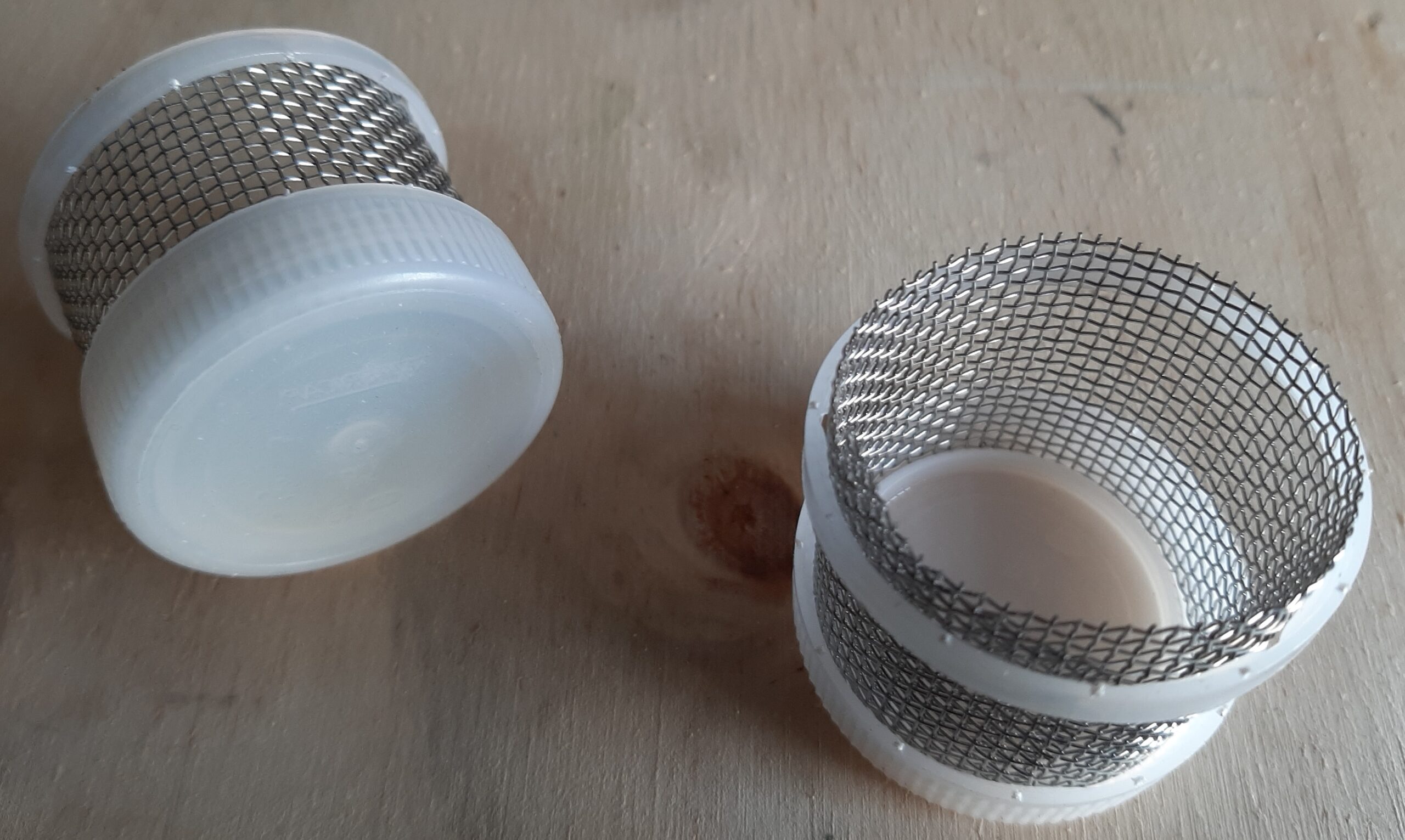 cut with tin snips or a hefty pair of scissors. I rolled a strip gently and placed one side of the cylinder into the cap off a fruit juice drink bottle ( the ones that are about 1″ diameter) and temporarily restrained the other end of the cylinder with the security band that was left on the bottle when I opened it. This was “glued” together with fibreglass resin poured into
 the upturned cap. Some of the strainers needed sewing together with loose pieces of the stainless wire but others could be fixed together with a “dot” of resin through two layers of mesh. Once the resin had set I drilled a hole through the top to be able to insert a short piece of aluminium tube,
  this needs to be carefully set to provide a small gap between the tube and surface when the whole thing is stood on the end of the mesh – 2 or 3 mm gap should be enough. A few drops of superglue to hold it in position and you have your strainer and uptake pipe. I
 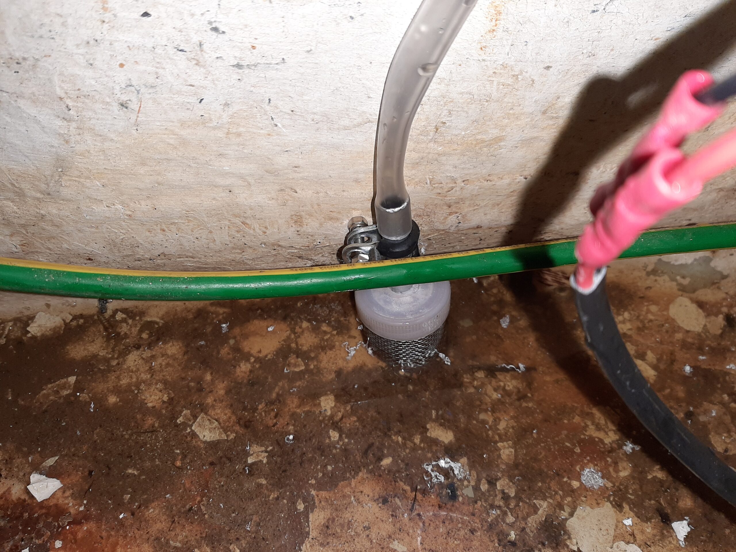 mounted some of my strainers using the same aluminium bracket as the matching level sensor. The rubber lined metal P clips are great for this as you get a firm hold but can adjust the position a little. If you left enough room when setting the tube height I think you could also “glue” the strainer mesh to the hull using resin. This picture also shows the sort of crud I was needing to keep out of the pump heads. This particular one was in the main locker that had been half full of water for a year or so and was not cleaned out and painted yet.
The tubes were basically treated much like the wiring and bundled together using cable ties and occasionally mounted to a suitable piece of wood using nylon P clips. The outlets of all of the pumps were run to the engine air inlet hole in the cockpit along with the syphon break valve vent pipe. Not the neatest solution but I will know if any of the pumps has to run while sailing.
Water level and temperature sensors
The water level sensors are bought in ready to use. Like all of the boards intended to be used with Arduino or Raspbery Pi computer boards they have plug and socket connection capability and run off 5V so are safe to be immersed in water.
You can find several vendors offering exactly the same item on ebay. Mine cost me £1.92 each.
The sensor produces an analogue voltage which is proportional to the amount of water that has covered the parallel strips on the circuit board. However I dont want the whole of the circuit to be immersed in salt water so the non-sensing part will need to be protected somehow.
If you have read the bit about corrosion you will also realise that immersing powered items in water is not the best thing for corrosion! As a consequence I want the sensors to be powered off for most of the time and to have both the 0 and +5 volt wires connected to the galvanic grounding network when the sensors are not being actively read.
As the boat will be based entirely in the UK, I also have to be aware that the temperature will eventually go low enough for rain or condensation to freeze. Not a situation where you want to try to pump it as any super cooled water will suddenly freeze when shocked. I also want some of my sensors to include a temperature monitoring capability. Again there is a board that will do this but you can also build your own because it is basically a thermistor (temperature dependent resistor) in series with a fixed value resistor. 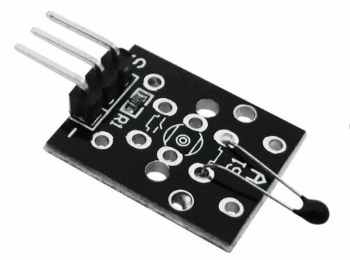 You apply 5V across the pair and measure the voltage across the thermistor – As the temperature changes so does the proportion of the applied voltage that you read on the output. I bought 2 of the ready made boards because that made it easier to mount the thermistor so it is just on the surface of my encapsulated sensors.
As my sensors need to be a long way from the computer board I wont be using anything like the usual arduino plug and play cables so I removed the plugs from both boards, connected together their + and – tracks with thin wire and added a long piece of 4 core screened wire. 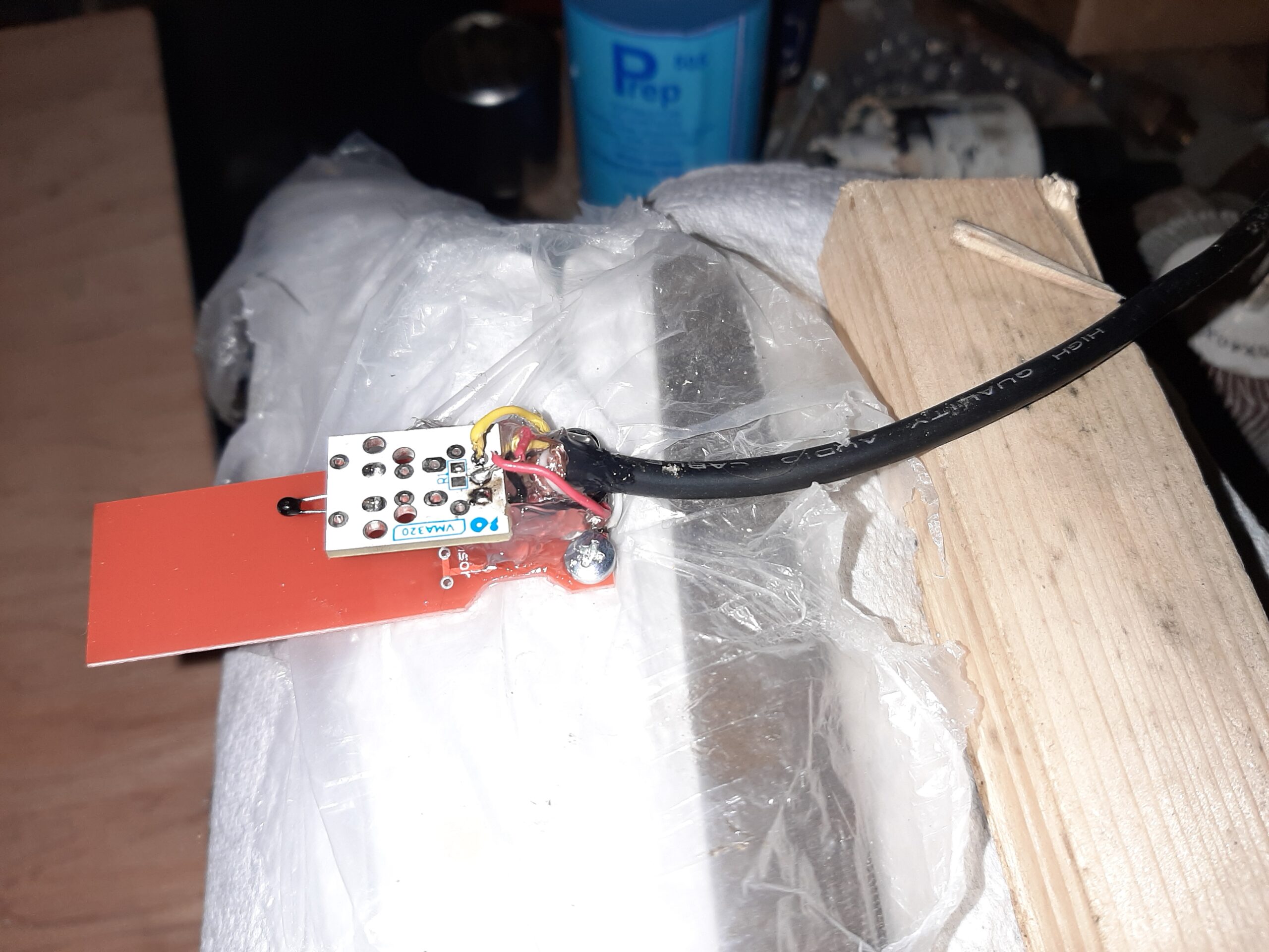 In my case the + wire is red and the – is black (boringly conventional), the temperature sensing lead is yellow purely so the water sensor used the remaining
  wire and I can use “white water” as an aide memoir as to how it is wired (Massively old throw-back to the Black River near Watertown, New York. Photo credit Dr Fadia Homeidan).
Ok so now we have to waterproof two sensors like that and two which just do water level. but first I added some silicone between the two boards and around the end of the screened cable so no stray connections can happen and put two 3.5 mm bolts through the mounting holes, hold them in place with a nut followed by sleeving and finally another nut right at the start of the thread. I tried to find a small plastic box that I could use as a mould to encapsulate the sensors but there was nothing suitable so just have to make a mould.
Step 1 was to make 4 copies of wooden blocks that were about the right size to be the final encapsulated blocks on each side of the sensor board. You will need something like an extra 2mm each side of the  sensor board and across the top and the temperature sensing board spacing (plus 2 – 4 mm) sets the minimum thickness of that block. I then drilled out a shallow hole in each of the blocks that were replicating the the cable side of the board and screwed these down onto a plywood offcut. Then I painted this with spray primer and then gloss white paint in the hope that silicone sealant would not stick to them.
Step 2 If you want a really neat finish, repeat using smaller blocks for the circuit side of the sensor board. Ideally this needs to allow all of the parallel strips to remain outside of the block and be the same width as the blocks made for the other side. You will also need some dowels to create holes to put the mounting bolts into
Step3 Build an open top box on top of each of the boards using plywood strips 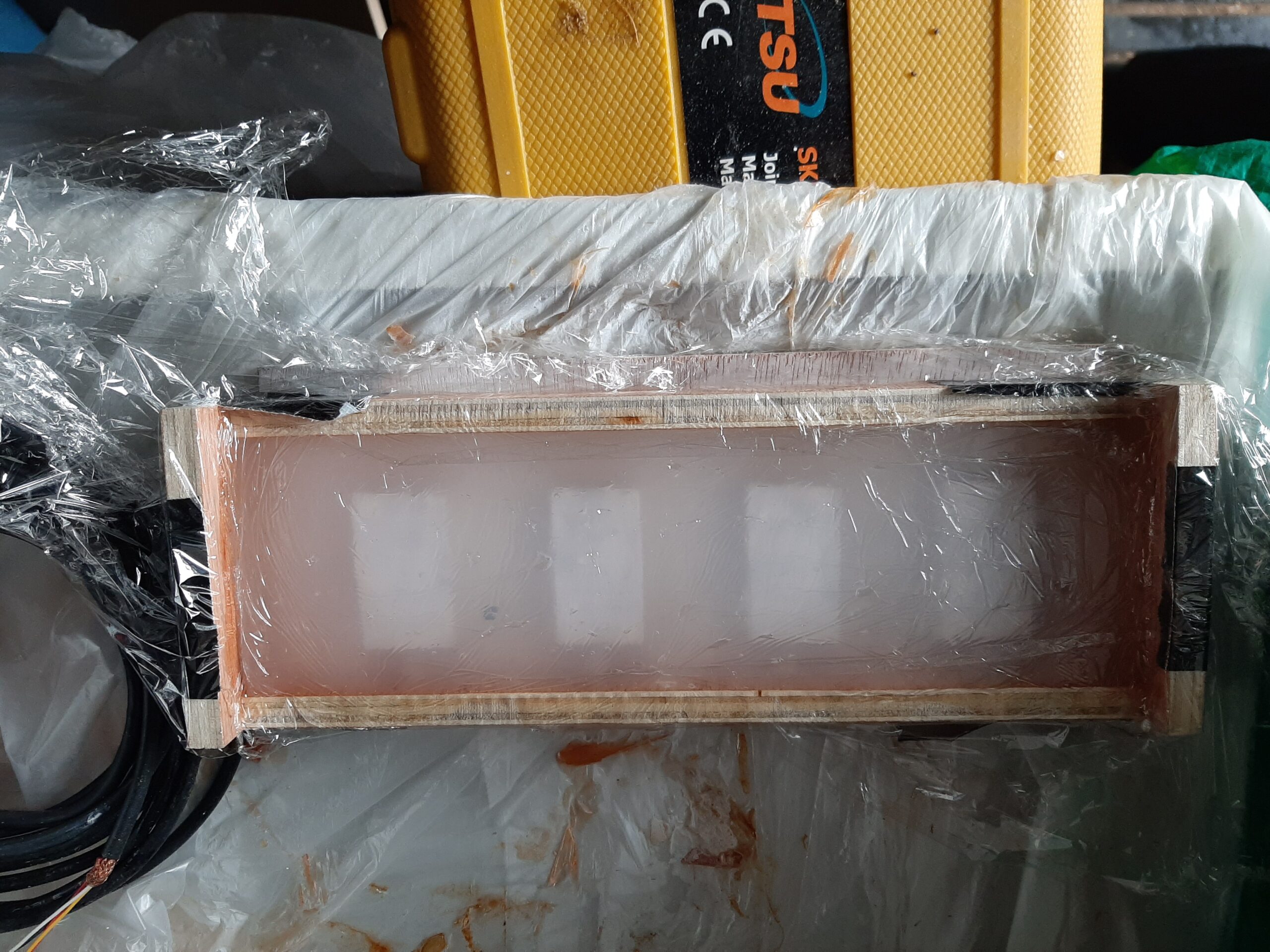 and duct tape. Fill each of these with silicone sealant making sure it is coated nice and close to the surface of the blocks and there are as few air bubbles as possible. Any old cheap / scrap sealant will do as it’s not going to be part of the finished system. Leave these for as long as it takes to harden right through. I think it helps to keep the moulds in a humid place as moisture helps the silicone to set but dont put them in the house unless you want a few days with a strong smell of acetic acid.
Step 4 Take the frame and base off and carefully remove each of the  wooden blocks. You now have flexible moulds to use for embedding the sensors.
Step 5 I used proper electronics potting compound but you could use any resin that is non-conductive and sets reasonably quickly. The potting resin is intended for professional use and comes with all the material safety documentation. Wear gloves like it says – This stuff is epoxy resin so quite good at sensitising you to the chemicals but it is really very well packaged to make it easy to use safely. The two parts of the compound are separately sealed in a bag with a clip to prevent them mixing. To use the potting compound you remove the middle clip and massage the bag until the clear and black components are well mixed. Cut off a corner of the bag and squeeze out the resin into the wells of the mould with the notches for the cables. Now add the sensor boards making sure they 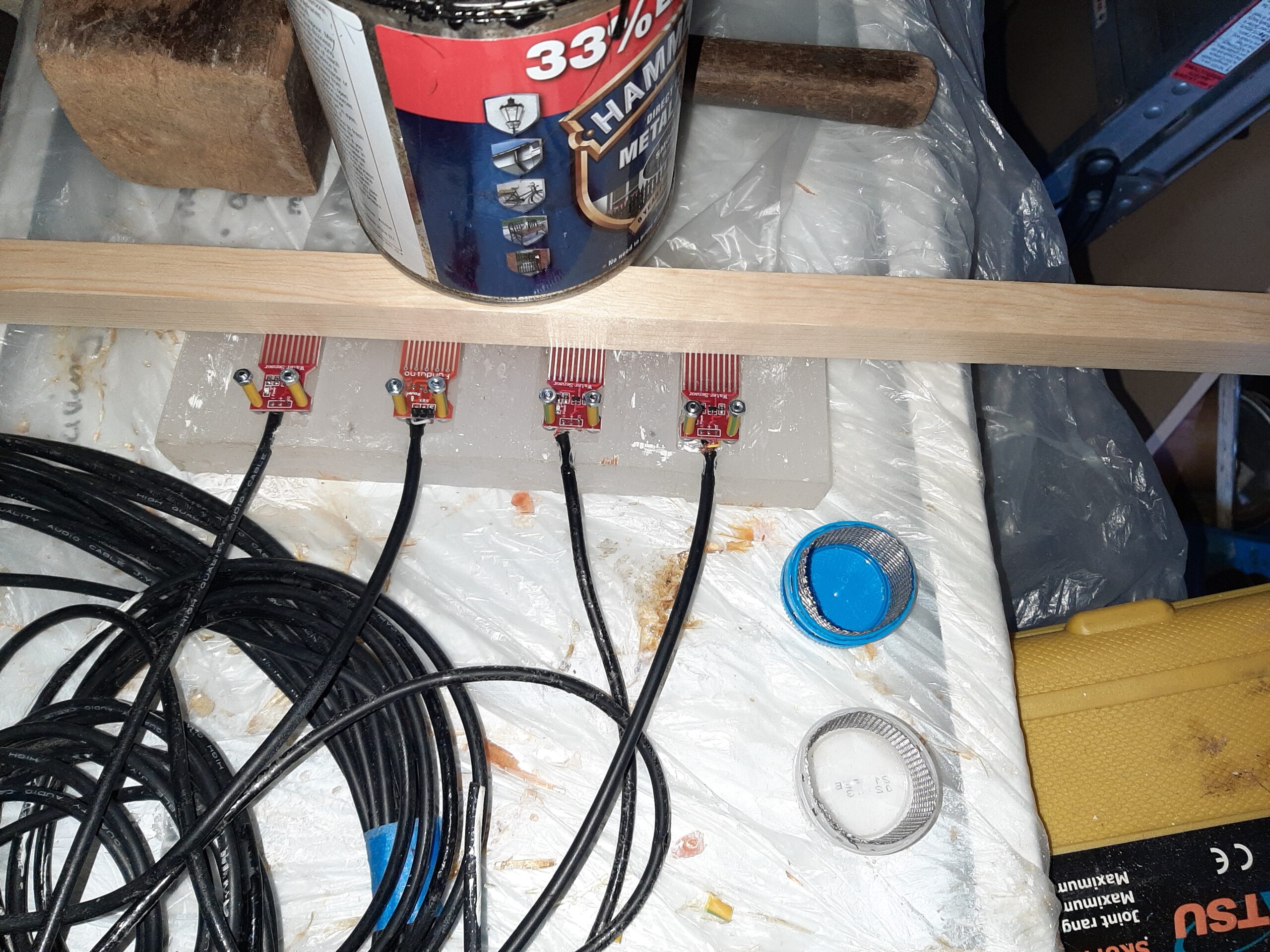 are pushed down into the mixture well, wedge or weight them in so the sensor board sticks out and the wire is in the groove left for it. Add any more potting compound as needed to bring the level up at least to the top of the mould. For a quick and scruffy job you could coat the upper
 side of the sensor by just pouring on potting compound up against a barrier like that wooden batten and doing a bit more tidy up afterwards. Leave the potting compound for as long as it needs to set – 24 hours should do if it’s at room temperature but I did this part in the garage and left it a couple of extra days because it still felt sticky.
Step 6 For a neater finish, remove the half potted sensors from their mould, trim off any excess compound that goes beyond the intended edge of the blocks and repeat as above using the shallower version of the mould on the second side of the sensors.
Step 7 tidy up the encapsulation using sandpaper and / or a file but go carefully and dont 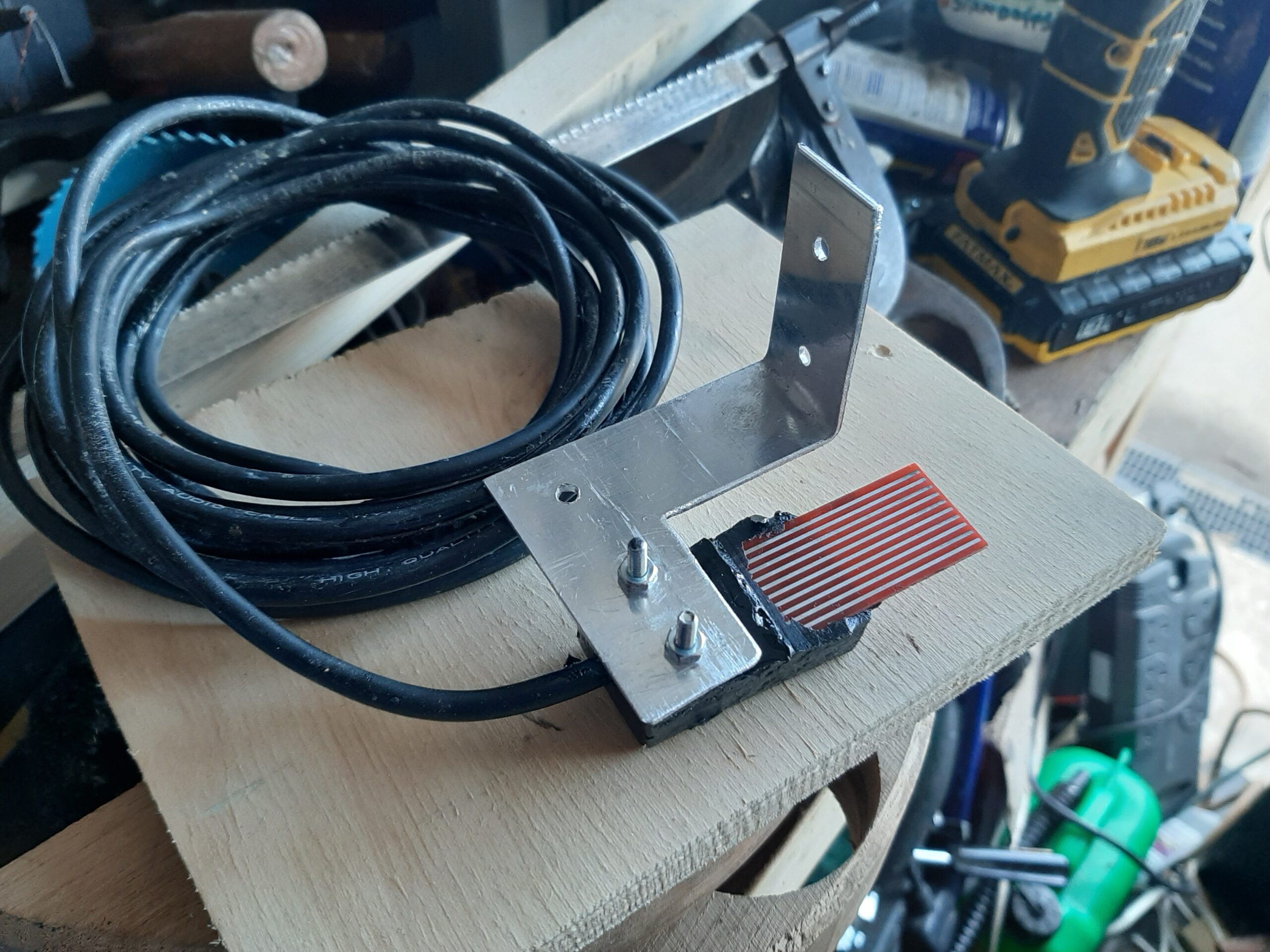 damage the exposed copper strips or you will have to start again. Add a suitable aluminium bracket to position the sensor and inlet strainer. How professional does that look ?
Relay board You need to be careful in selecting the relay board to use with this project as the relays on most boards are switched on via taking a computer pin to the low level. I realised just in time that this would mean the relays were potentially triggered when the arduino is in sleep mode. We need one which is turned on be a high level signal.
The other design requirement is the ability to handle 12v switching and the current required by the pumps. I only have a digital meter which is not very good at indicating anything other than the continuous running current for the motors. I would expect a really good analogue meter to show a transient startup current much higher than the steady running one.
This is the type I used because the picture on the internet shows relays  which are capable of handling 10A at 23V DC and you can set it to switch on via either a low or high level signal. This needs a 5 volt feed to drive the relay coils as well as the on/off signals for each relay and the relays are electrically isolated from the driving computer which means there will be no chance of the computer chip being damaged or software glitches happening when relays switch on or off.
The relays are sealed but I still bolted the relay board into a waterproof plastic box which was eventually screwed to the side of the engine 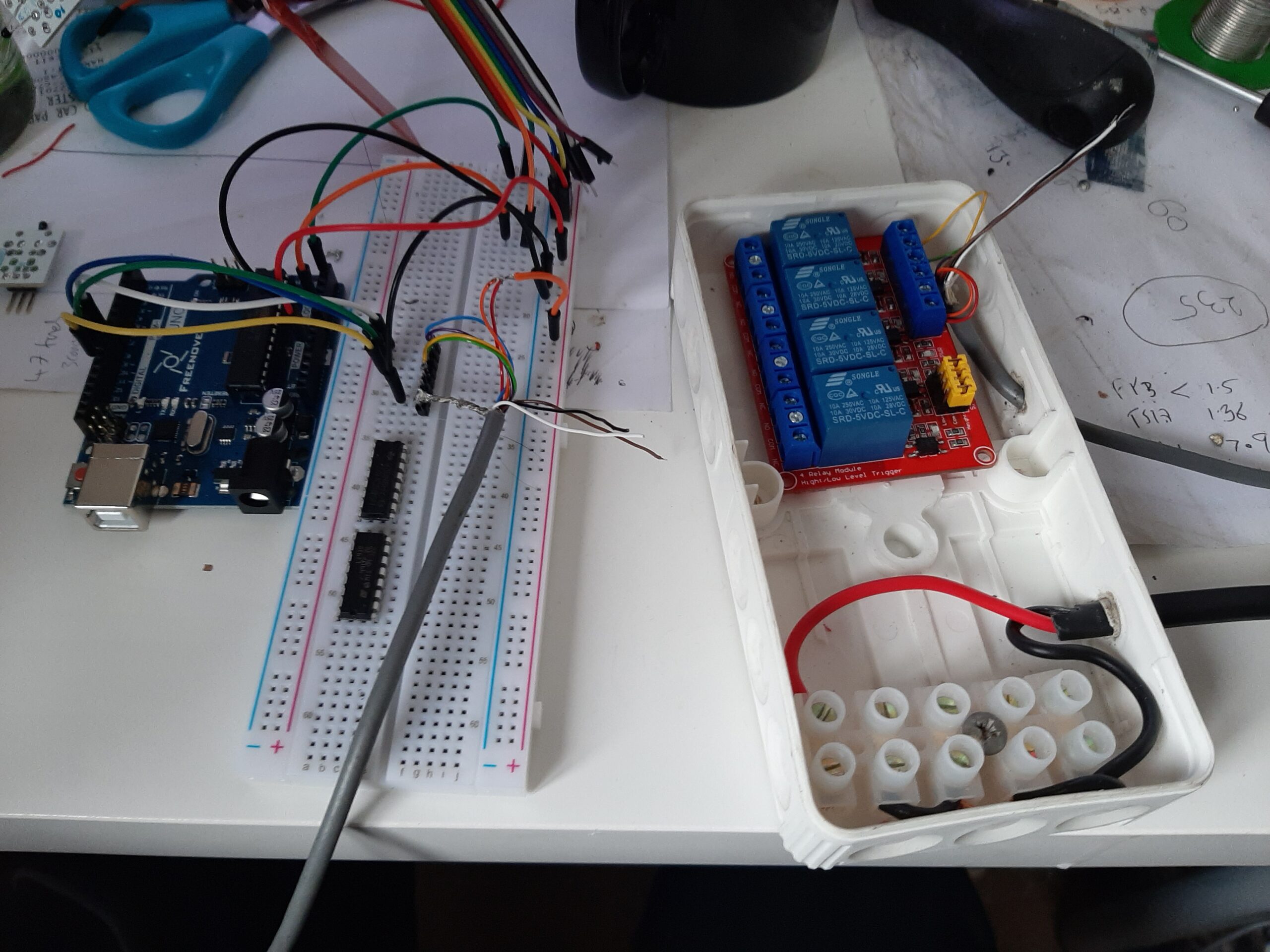 compartment almost at the top (Another attempt to keep water out of it). The photo shows the box connected to the arduino board during software development. The red & black pair bring in the 12 V power from the bilge pump circuit and the screened multi core wire is the 5V power for the switching circuits and the four control leads. The four pumps are wired to the choc block for their negative supply and the positive goes to the corresponding relay. The multi coloured ribbon cable at the top goes to the sensors and at this stage the coffee mug was simulating a part filled bilge compartment with or without an added ice cube.
Arduino board and other circuits
For the software development phase the Arduino was connected to the required components using the patch cables and experimental  “breadboard”. I think this was at the first operational stage so the sensors were wired to separate analogue inputs and switching the correct relays according to suitable level signals. Still to add the power down feature, time limits on the pump run, timer based wake up signals, use of a selector chip to feed multiple analogue signals into a single chip input line and temperature inhibition on pumping.
Once each stage of the electronics and software were working, I progressively transferred each part of the circuit to a sheet of vero board (perf board to any US readers). This includes two voltage regulators connected in series because the maximum voltage of a fully charged lead acid battery is close to 14V and the 5V regulator required for the arduino input cannot handle that directly. I could have just 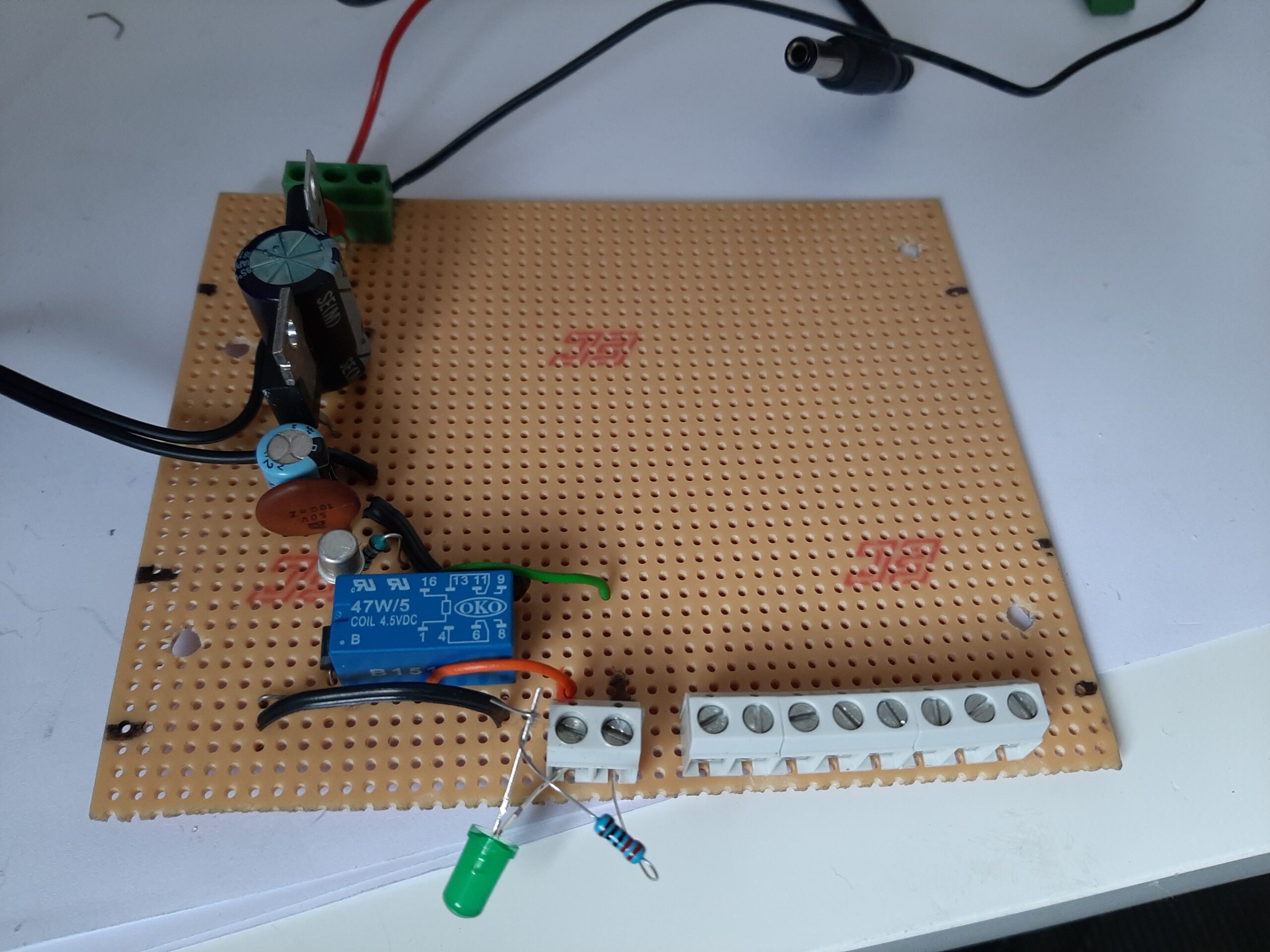 added a resistor but as there are five relays to drive there will be a significant difference in the current required and it seemed easier to drop the 12 to 14 V supply to a regulated 9V first. The 9V and 5V levels are both smoothed using electrolytic capacitors and an RF shunting ceramic capacitor. That and the on board regulator & RF suppression should prevent the computer interfering with VHF radio or being disrupted by ignition or generator interference.
The relay on the picture above is the one which controls the power down feature for all the peripheral systems and ensures that all water level sensors have their +5 and 0 volt wires connected to the galvanic grounding system when not being actively read. – The LED and resistor were temporarily installed instead of sensor and relay systems to test that aspect of the software.
The arduino was really easy to mount in the boat as it arrived with a mounting plate which it clips into and which can be attached with bolts or wood screws. I fiberglassed a couple of small wooden battens across the cabin wall at the back of the port electrical box and screwed the 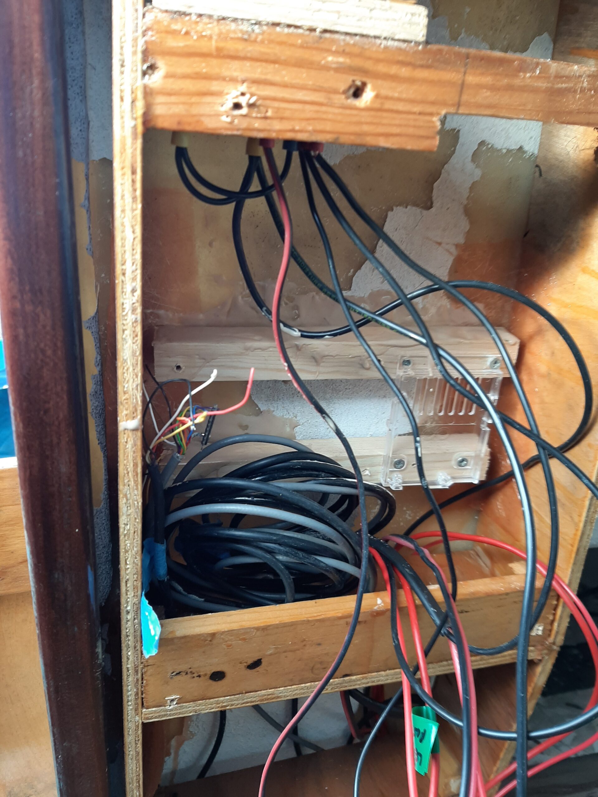 additional board and arduino mounting to those. There is just enough depth for the vertically mounted components on the add-on board and the switch panel to fit.
Once all of the cables are connected it is a complete rats nest because of the number of sensor wires but it seems to work OK.
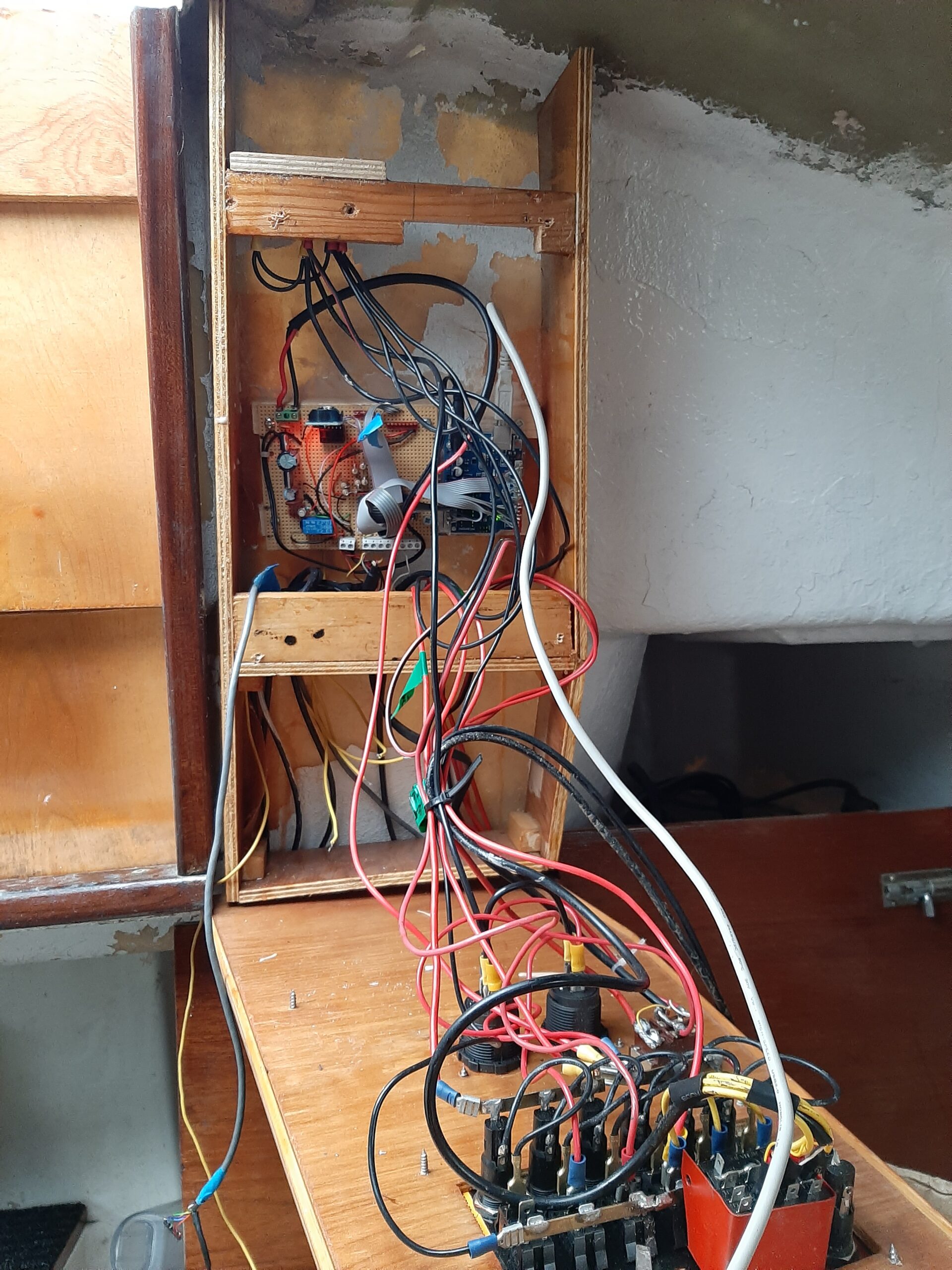 This picture shows the first operational version of the electronics board being installed. This runs the pumps and sensors via the analogue input selector chip and applies all of the required timing features. Battery charge levels are monitored via a divider network to bring the 14V maximum charge to below the maximum 5V for the arduino to read. At present the only readouts from the system are via the grey USB lead to the laptop but you can tell it is working via the gentle sound of the power up relay as water levels, temperatures and battery levels are checked every 5 minutes.
For the future I aim to add the ability to record water level readings, battery charge levels and pump run times on a memory card. The same division ratio as the battery monitor will also be applied to each of the main bilge pump motor inputs so that the computer can wake up if a pump is triggered by a float switch in just the same way the timer currently brings it up from power down mode to check for more subtle water ingress.
At present (27/10/2020) the system has been running continuously for over 3 months using the solar panel to replace the electrical power used. So far it hasnt had to trigger any of the pumps but the wetter weather is beginning so I probably should be working on the data 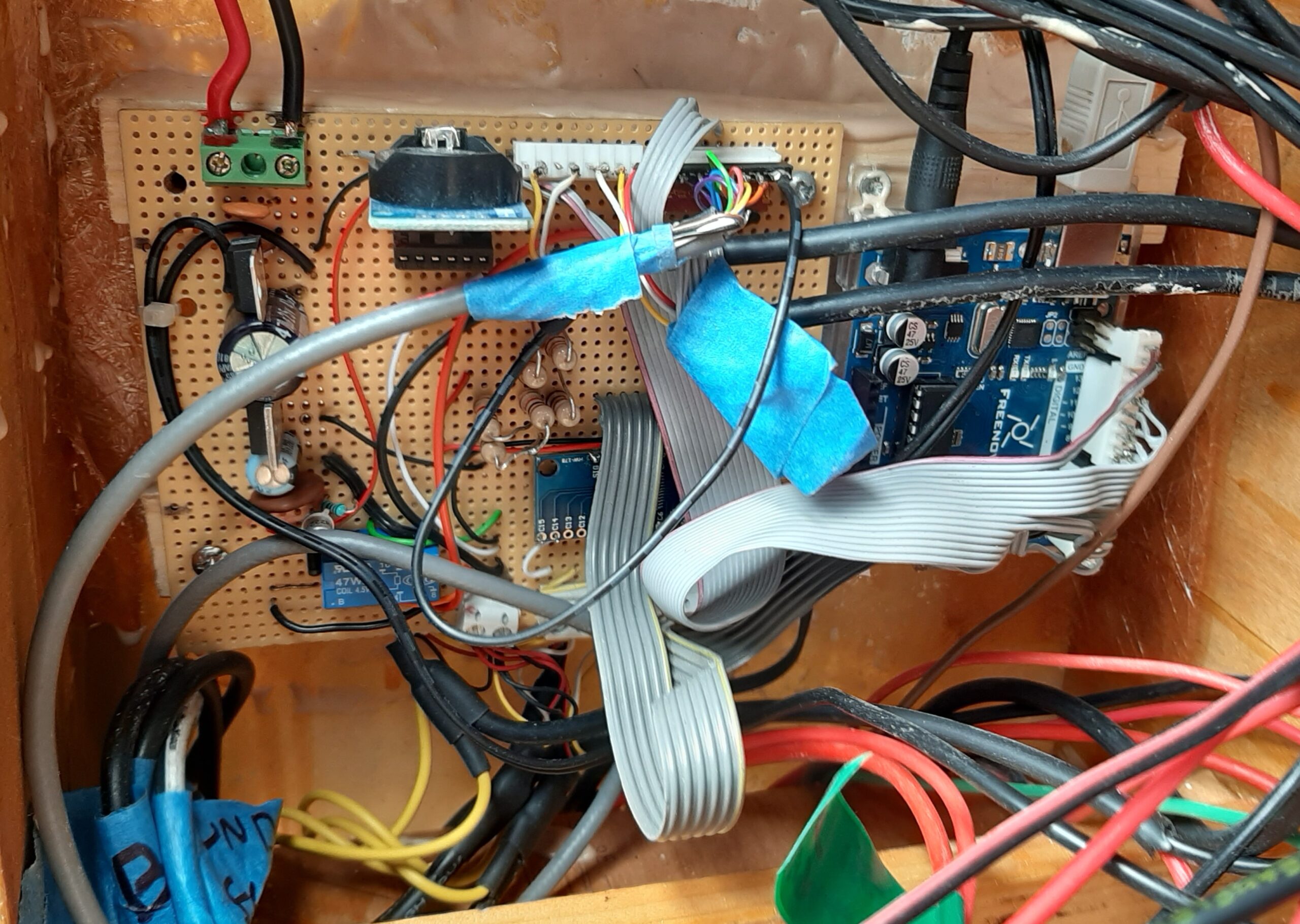 recording aspects soon so I can keep track of whether it has to pump. I have all the required components and a “spare” arduino to develop the software on before I plug in the memory card writer into the add-on electronics board and load a new software version.
Main bilge pumps again
During that slight distraction the other two main bilge pumps were installed with the outlet pipes crossing over above the passageway 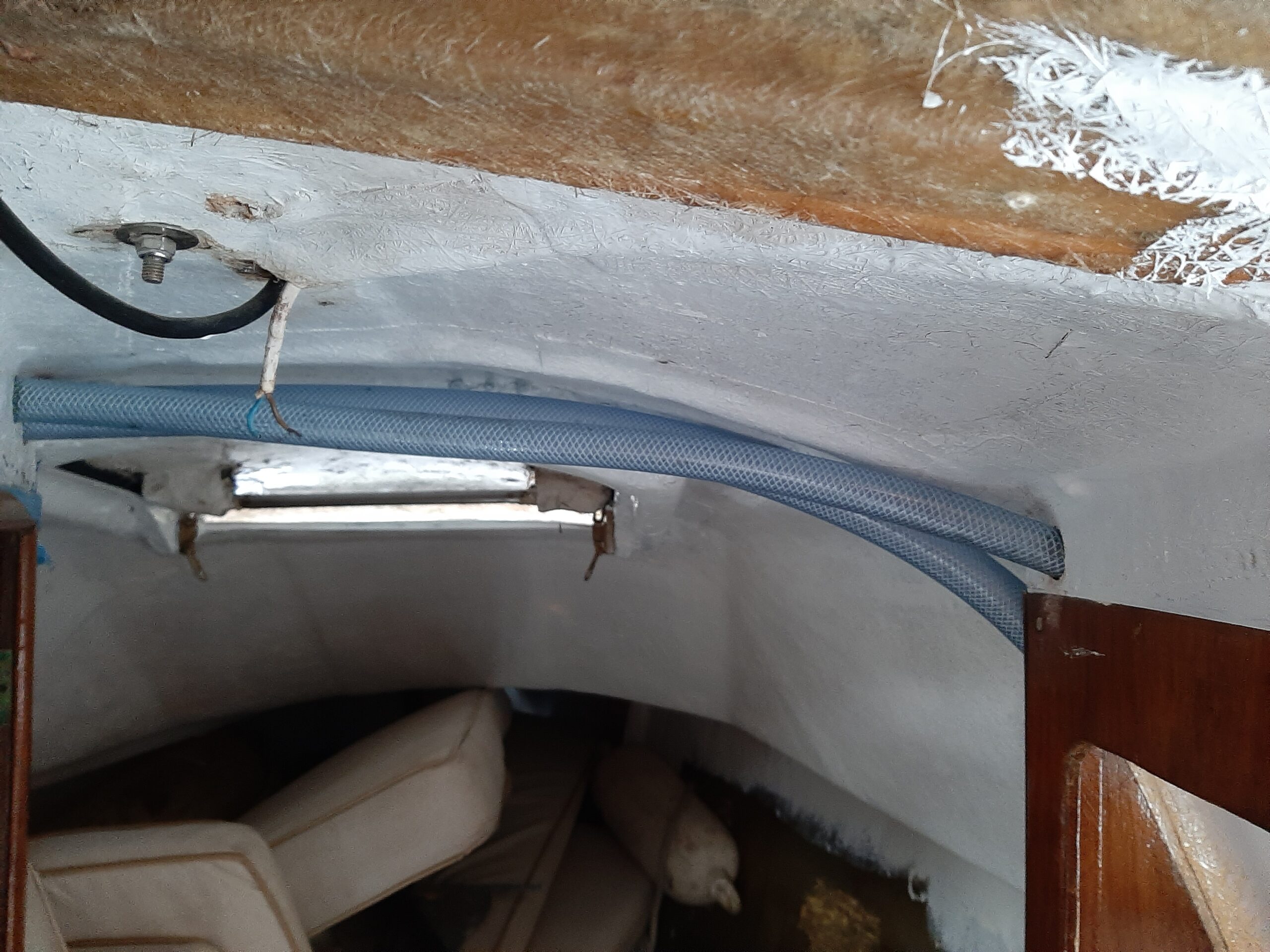 between the main cabin and fore cabin. The one in the main locker has
 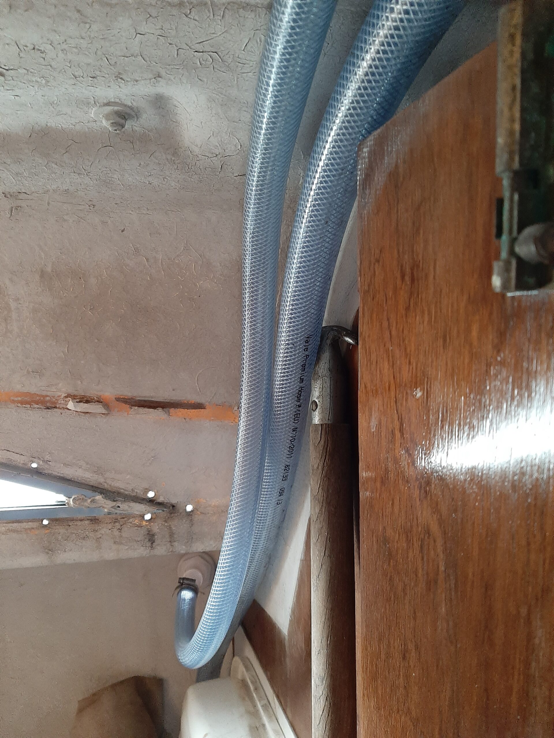 a pipe that crosses the heads
and then exits on the starboard side in the fore cabin while the one in the locker under the V berth goes through the hanging space to a skin fitting in the heads compartment. This was completed at the end of March, at roughly the same time that the bilge drier sensors and wiring was being installed in the same areas.
Wow!!! Such detail and thought put into this restoration. I need to study this again and hopefully derive useful ideas towards my ongoing Snapdragon improvements.
Thanks Frank. It’s taken a long time but with what was essentially a blank canvas you can and need to make well researched decisions. I will only know what I got wrong after the re-launch though. There’s bound to be a few things that need a re-think.
Sorry I didn’t reply quicker but we had a major computer crash and I have been re-building it and trying to recover software and passwords etc. Finally able to get to my stash of saved emails today so I got the site management link back.