Tuesday 19/9/2017 – Temporarily put the exhaust “Resonator” back on the engine so I can measure control cable movements. Assembled the new control lever box with the cables in the right places for the movements required. With the gear mounting adapter in it’s current position it needs around 3cm to move from neutral to forward gear and another 3 cm from neutral to reverse. That is correct for the available movement as the alignment with the current position looks reasonable and I can easily move the mounting block up or down the lever if needed. Throttle shaft needs to move round just under 90 degrees with about 7.5 cm total movement of the cable.
Thursday – Mainly design ideas for the throttle linkage and component searching to know what is available and practical.
The remote control cables end with a M5 thread and the gear lever already has a 8mm diameter ball fitted. The gear shift has now been greased and is easier to move but I think it will still need a metal connection rather than plastic. Both of the dimensions will match these two metal ball joint systems. –
http://www.gsparkplug.com/1x-csa009-metal-ball-joint-m5x1-0-csa009.html (£3.56)
https://www.carbuildersolutions.com/uk/heavy-duty-ball-joint-m5-rh-thread (£5.40)
Friday – Still undecided how to do the throttle linkage because, as well as the remote control, I will need to be able to adjust it from the engine when starting from cold. Also it will possibly need to change the angle and amount of movement as the remote control cable moves fore & aft 7 cm but not in a place where I can easily have a long enough lever rotating on the carburettor.
Sat 23/9/17 – Did some fabrication for the throttle linkage so there is now a lever attached to the throttle shaft and a pivot bracket attached to the carburettor mounting stud nearest to the flywheel. Next I need to make a lever with a series of holes around half way between the pivot and the control attachment. Need about 4.5 cm movement at the attachment of the link wire.
Sun – Started by cutting and drilling the throttle lever for the engine.
Set up the workbench ready to try out the mig welder as a method of attaching a M6 bolt to the throttle lever to act as the pivot. I will need to move around most of the disability scooters to get at the welder so the actual task will get done later in the week.
Overall a very productive weekend even if most of it didnt fit with this particular blog theme. Alongside my boat there are three horsebox conversions and a camper van restoration in progress.
Monday 25/9/17 – Welded the bolt to the back of the throttle lever. Not a particularly neat weld but I need to get used to the speed that the wire advances and there was not much of a weld to do. After the struggles with a hand held visor when I was welding the trailer with the stick welding system, the self darkening helmet seems strange as you can see what you are doing before the arc strikes and then continue to see what is happening. Still doesn’t help though when the wire shoots out fast if you press the trigger and the wire misses the work piece. I guess I will get better with practice and trying at night without my glasses on might also have made it a bit more difficult.
Filed off the worst of the lumps and spray painted all three pieces of the mechanism.
Tuesday – Assembled the throttle lever before setting off to work. 
 Once the lever is connected to the remote controls I will make an appropriate length coupling rod between the control lever and the throttle arm on the carburettor. The stainless steel wire from the inside of the original control cables will do that job fairly well.
Wednesday – Spent the rest of the evening trying to sort out the rest of a shopping list to get the engine ready to re-fit.
- Also ought to get the cooling water pump re-installed. Another £112 for that order which includes the fuel filter.
- Anode for inside the cylinder head.
- Also need to find a source for a copper washer to seal the brass plug. Don’t want a doughty washer or fibre washer for that one as we also need a good electrical connection.
Thursday – I think tonight’s focus might be on making up some saddle clamps to attach the control cables to the engine. The M5  threaded mounting points are present but I need to add something to clamp the cable outer and also ensure the cables don’t slip out of alignment. First thought is something like this made from some of the stainless steel plate. Will need one for the throttle and one for the gear cable and maybe one for the spares kit because they are exactly the sort of small but essential part that will go missing in the bilges if a control cable ever needs removing.
Friday – The thread die had arrived but when I tried to use it to tidy up the rusted threads on the engine mountings it became obvious that the threads are not 3/8” UNF but something just a bit larger. Another tool to add to the collection of “wrong size” threading equipment. Might have got it right first time if I had a thread gauge but I have revised my theory and now think these must be M10 x 1.0mm pitch which is a standard fine pitch metric size (normal M10 thread is 1.5 mm pitch). Dimensions are very close – 25.4 TPI for the metric thread and 24 for the UNF and external diameter will be slightly under 10 mm rather than 9.5 mm. Not easy to distinguish when the threads are distorted by rust but the UNF die would not fit because of the core diameter being 0.5 mm oversize. Not as easy to find the fine metric die at a sensible price but I have ordered a carbon steel one for £9.60 from a supplier that is new to me (alternative suppliers wanted £30 to £40 for a HSS one before adding delivery charges). At least I hadn’t also wasted money on nuts before discovering the thread is different.
Saturday – May only have been 5 holes drilled, 3 hacksaw cuts, a few minutes filing and some bending with a hammer while clamped in the vice but I now have some two suitable control brackets.  Need to cut some rubber to go between the cable and the exhaust resonator (because the bend is not particularly accurately placed on either bracket) and make some saddles or plates to clamp the cable in place. Would have been a lot easier if they were made of aluminium rather than 2 mm stainless steel plate but we need the strength of the brackets to ensure the remote controls are going to be reliable.
Tuesday – M10 fine thread die has arrived by post today. Finally got to test the threads on the engine mounts which are indeed M10 fine pitch.  Threads tidied up nicely on the two that are here. Took a time to get to that stage but it is one more piece of prep work out of the way ready to put the engine back. Still have to clean up the other one and replace the threaded portion of the third. Can probably do that using a bolt and some of the rubber mat offcuts from the trailer.
Wednesday 18/10/17– Went to storage at about 1:00. The cover was partially off but otherwise no problems cause by the recent hurricane remnant (I never thought I would be writing anything like that about english weather).
The waterproof stop switch is installed in the control recess but still needs some silicone sealant inside the locker to make sure the soldered connections are waterproof.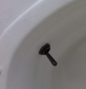
Removed and brought home the third engine mount with a threaded section. Part of the thread has been tidied up by using a mole grip to stop it turning in the rubber but this is currently another un-finished task because to do the rest I probably need the M10 fine thread nuts to grip the thread without damaging it.
Thursday 19th – Cleaned up the rest of the exposed thread on the third engine mount. This one has damaged rubber so the “bolt” will come right out of the vibration damping rubber. Meant I could clamp the head of the bolt in the vice and run the die up and down a few times. Did end up with quite a lot of WD40 inside the rubber but that will hopefully dry off and mean I can inject some silicone sealant to stick the bolt head to the rubber component. I will eventually do something similar with the fourth mounting unit but that needs the rubber replacing between the bolt head and the engine bearer.
Saturday 20th – Went to storage just after 5pm. To follow the hurricane last week we have storm Brian this week and it seems to have arrived while I was on the way with drizzle to start with but increasing as the wind strength grew. The boat is effectively parked stern on to the wind so the rain was blowing into the cabin and I didn’t stay to do much beyond an hour.
Had to do a bit of hole enlargement to get the remote control cables through the locker base and the general impression is that I need 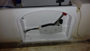 slightly longer Teleflex cables because I underestimated how much cable is inside the control and how much is lost in getting out of the locker into the engine space. The brass piece will just about stretch to line up with the rearmost bole in the engine bearers and the cable mounting groove needs to be about there. The ones I bought were 5 foot so I should have got 6 or maybe even 7 foot cables. At the moment marinescene who I bought the original cables from are having a sale so each replacement 7 foot cable will only cost £1 more than I originally paid.
Sunday – Only boat related practical achievement is that I have ordered 4 Zinc pencil anodes which I need for the engine (with 3 spares / experiment parts) and a 2.7 Kg bolt on anode to protect the rest of the metal. Almost exactly half of the cost is goods, the rest is postage and VAT. Would have been worse if I hadn’t ordered the bolt on anode as they seem to charge £13 for postage regardless of the weight and size of the items purchased. Could have saved that if I was anywhere near their foundry in Kent as you can pick up the goods.
Hopefully will get the anodes sometime this week so I can install the pencil anodes on the brass plugs which is the last step before re-fitting the exhaust onto the engine. The anodes have a ¼” whitworth male thread on the end to fit a brass plug. I think the holes in my plugs are too large (need a 5.0 or 5.1 mm diameter hole to tap 1/4 whitworth thread) so I may end up heating the plug to “tin” it with zinc from one anode and then either tap into the zinc or sweat that together with the working anode. Alternative is to accept that I need a better electrical connection to the engine than I am likely to get by tightening the plug into a rusty / painted piece of cast iron with a copper washer and to fit a piece of threaded rod through the brass plug and into a tapped hole drilled into the anode. Then I can have a screw fitting to attach an engine grounding wire to the plug. At least I will have 2 plugs and 4 anodes to experiment with.
Wednesday 25/10/17 It is the end of another full month of boat ownership and again there is not a lot of progress to show for it. Electrical system is live but no progress at all with the bilge pump plumbing. Made some progress with the ignition system and the rest of the engine should be all sorted early this month as the anodes are on their way.
Ordered the longer control cables, hose for cooling and bilge pumps and jubilee clips for those plumbing projects and the stern tube.
Saturday – The longer remote control cables have arrived so I fitted them to the control unit and went to storage to install the controller in  it’s niche. Now have plenty of spare control cable as the photo shows the engine ends lying on the forward end of the engine bearers. Not yet bolted the control body into position because I cannot find the longer pair of bolts which came with it. They may have gone down behind the freezer because the last time I saw them they were still in the bag which I was keeping on top with the assembly instructions. Once the position of the control unit is fixed I will need to put some sealant round those cables where they go into the locker and also where they and the wires enter the hull from the locker. That is quite a large hole as it also has the mains input cable, car charging cable, engine stop cable, stern nav light and compass lighting cable.
Sunday – I have been thinking about the bilge pump plumbing as the hose is due to arrive tomorrow. At least with the plan outlined below I only need to install the stern compartment’s pump plumbing before the engine goes back in.
- Bow area pump is obviously going to be in the locker under the V berths as the rest of the fore cabin is linked to the main one. At the moment I think the pipe should go up to the cabin roof then do a 270 degree vertical loop to keep out any spray or solid waves that get that high and then go out through the side of the cabin onto the side deck. That will minimise the pipe run without putting a hole in the hull at an area which might go under the water if sailing with a serious heel. If there is sufficient flat cabin side it is probably best to do that on the port side of the boat as the pipe loop can be mounted against the toilet bulkhead.
- Midships pump might be practically placed in the galley storage under the cooker with a similar 270 degree turn located inside the hanging locker. Again high enough outlet to be always above water but minimal pipe run. Will need to install scuppers to let any water from the cabin floor into the bottom of the locker and possibly closable ones in the under bed locker and from the heads compartment into the cabin. I don’t want water getting in the battery locker and the main under bed locker if it is in the cabin or engine spaces but may need to be able to empty those spaces if necessary. Maybe need a fourth low capacity pump which can plug in when needed.
- Stern (engine) compartment pump can be alongside the engine close to the removable engine partition. This one will have a longer pipe run to an outlet as high as possible in the transom or alongside the manual bilge pump discharge. As this run does not go through the cabin space there cannot be as high a loop to keep out backflow but that shouldn’t be a problem unless there is a serious swamping from waves coming from aft in which case waves breaking into the cockpit is a much bigger risk than the bilge pump discharge. That risk is not helped by having two air inlets at about half the cockpit depth which go directly into the engine space and the cabin. Might need to do something to be able to block those vents properly if needed in an emergency.
- Float switches for the three individual pumps will be close to the pump itself as close as possible to the bottom of the compartment. A fourth high level switch will be in the engine compartment positioned above the bottom of the engine opening so it triggers all of the pumps if there is likely to be water getting over the top of that partial bulkhead.
Monday – Unpacked the parcel with all the bilge pump and engine cooling pipe. Hopefully I will be able to take that over to the boat tomorrow so it is in the right place to get installed once the hull fittings are in place.
Friday – Today’s interesting piece of post was my set of anodes. I wont fit the big bolt on anode to the hull until after we have finished painting but the zinc pencils can be fitted to the engine this weekend and, once that is done, I should be able to find enough bits of random time to be able to properly assemble the exhaust “resonator” onto the engine.
Saturday – Woke up before 6 and couldn’t get back to sleep so I was in the garage by about 6:30. Started with a bit of a tidy up and marking out the cuts I need to make to create the clamp straps for the remote control cables and an additional bracket to attach the belt cover to the starboard engine mount. Didn’t actually cut them out though as everyone else is still asleep and hacksawing is fairly noisy.
Started to drill the brass plug a little wider so that the zinc pencil can get at least 5mm of it’s thread in the brass plug. Basically need to widen out the cast in hole so it has a 10.5 mm diameter section a few millimetres deep. If I let it in about 4mm the whole assembly will be short enough to install without taking the resonator off again. Unfortunately I didn’t have the drill set with me so couldn’t drill out the pilot hole that I need for tapping the ¼” whitworth thread (Ideally 3/16” which means 5.0 or 5.1 mm).
Tuesday – I have the next 2 days off work and hope to get some progress made with the boat as well as taking Matt to storage so he (or is that we?) can work on the Tin Can Kitchen. Depends on the weather but my priorities for the on-boat jobs are-
1. Engine space bilge pump outlet and plumbing.
2. Mounting bolts for engine control (probably not stainless steel at present as I just want it fixed in place)
3. Remove cabin hatch cover, paint sliding hatch and inside of the cover. Replace with mastic sealant & pop rivets.
4. Clean up threads on anode mounting studs (+order nuts required to mount anode)
5. Remove window(s) so can clean up & replace sealing rubber (+order stern tube rubber).
6. Cutlass bearing mount
7. Clean, sand and paint cockpit floor and sides.
Thursday – As it is getting light, one look at the sky suggests today wont be like yesterday which dawned with a completely clear sky. At least one of the weather guessers said the two days would be the same so there is a lot of cloud to burn off if that is to be true.
Mostly working on the fuel system and sliding hatch today but those are another workstream so another blog post.
Friday Today I then ordered the bits to finish off the engine mounts, tap to fit the pencil anodes and some compression fittings to see if the nuts will complete the fuel handling system.
Saturday Woke slightly before the alarm so got a good start and was at the boat by just after 8:00. By the time Matthew phoned me just after 10:00 I had put sealant around the bilge pump outlet, installed the lower rudder hinge, waterproofed the soldered joints on the engine stop switch, done a temporary install of the engine control box with M6 threaded rod and put sealant around the cables where they enter the locker. Not a bad bit of progress especially when the rudder hinge  installation requires crawling head first under the cockpit floor to put on the washers and nuts and tighten everything up.
It’s not really this workstream but I still need to go back to the stern one more time as I realised the galvanic grounding cable did not have the 10mm end fitting on it so it has come home to be soldered rather than being fitted at the same time. Once that cable is in place I can clean and paint inside the hull and then regard that particular space as being ready for the engine re-install.
Thursday – The engine mounting nuts and replacement bolts for the fourth rubber mount have arrived along with the pair of taps needed to create the pencil anode mounting hole. Might get to work on that tonight if the authorising gets reasonably quiet.
Friday – We have a candidate for an excessive packaging award.  Yes I received a “free” copy of their catalogue with my order but that appears to have meant that two items which might have gone in a jiffy bag ended up arriving in a moderate sized box along with the best part of a whole box cut up as additional space filler. I do hope that they dont have any smaller boxes rather than being all about sending me the A4 sized catalogue when I can order everything I want from them online. Anyway, I now have my copper washer for the anode mounting plug (plus 24 spares) and a pack of ¼” compression fittings which might have nuts and olives which will finish off the fuel control valve assembly. So there is a task for the garage tomorrow morning and a non-weather dependent reason to go to storage sometime over the weekend.
Saturday – Some progress with boat jobs as a result of a trip to storage. The nuts on the recently purchased tube joiners do fit the previous fittings from green sparkplug so I brought all the bits home and did the final assembly for the fuel control valves.
I also put the newly purchased M10 fine pitch bolt into the engine mount which had the thread missing so there are now 4 working mountings and a choice of plain or nylock nuts to be used when it is time to do the installation.
Also soldered the grounding wire fittings ready to connect the lower rudder hinge into the galvanic protection network.
Wednesday 22/11/2017 – Matthew and Annabel have officially bought their house. Completion was Wednesday and by Friday they have already started the big scale renovation – Not sure how much of this will be their work and how much I will be a contractor on their project.
Each evening this week I have been sorting out the parts order schedule. Priority is now going towards finishing the engine refurbishment and installing those bits of the gas system that need to be in place before the engine goes back in. Only £184 worth of parts to get the gas pipe through to the cooker and the engine ready to run. Fuel tank, gas regulators and the stove will add another £300 to 350 around launching time depending on whether or not I go for a grill in addition to the 2 ring burner.
Saturday 25/11/17 – Matthew’s 25th birthday (Day 4 for the house and day 458 for the boat). Got to storage just after 8 and it was still very icy on deck. Installed the galvanic protection wire first as that was an inside job and I could keep the hatch closed to keep out the chilly wind. Then cleaned out about half the length of the fuel locker and painted the floor, bulkhead, hull side and cockpit side. I will leave it a reasonable time to dry as the lid was closed and the cover went back on something like 15 minutes after I finished painting.
Came home for about 9:30 and started on the zinc anode which is now fitted despite initially not having quite enough brass plug to take the thread. Ended up drilling the pilot hole until there was a dimple showing on the outside face and then tapping that as deep as I could.  Set up the electric drill as a lathe and used files and an old wood chisel to take off a few millimetres of Zinc so it fits into an 8mm bore into the plug. Seems that the anode is a firm enough fit in the plug now so I installed it with the compressible washer and tightened it up against a freshly sanded cylinder head surface (for the best electrical contact I can manage). If this works OK I have a spare brass plug and 3 spare anodes.
Tidied up the gasket surfaces on the exhaust system and cylinder head ready to properly re-install them. Drilled out one of the ¾” rubber tap washers to partially seal the water channel. To enlarge the hole in the 
 washer I drilled a couple of holes in a M10 washer and screwed it to a piece of wood with the rubber washer in between. I could then drill the hole to 10 mm. I then need to find a 27mm external diameter washer for it to seal against as the water outlet hole in the cylinder head is almost exactly the same diameter as the tap washer. Finished thing will look something like this in cross section –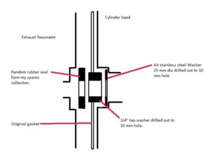
Also started making an extension to couple the flexible control system to the throttle lever on the engine.
Having searched through the bolts and washers in the garage I don’t have anything suitable for the water connection in the engine so tonight I went online and ordered an A4 stainless steel washer which is 25 mm external diameter (Will get another 99 as spares so picked M8 hole to be reasonably useful for other projects and minimise the need to remove metal and get a 10mm hole to match the rubber seals). At the same time I also got the M5 bolts and matching washers for the sliding hatch cover (again in packs of 100 so loads of spares) so that job will get done reasonably soon once I order the seals and the stern tube rubber which come from the same supplier.
Monday – There is a tracking email for the washers and bolts which will be delivered tomorrow. Maybe tomorrow evening I can properly re-attach the exhaust system onto the engine. The hatch cover needs other bits and some paint on the inside so if I do a trip to the boat I can bring the paint back with me and be one step closer to re-fitting that too.
Wednesday – The bolts and washers for the boat arrived today. Also did a pickup run to the boat to collect the aerosol foam insulation (for matt’s house) and the white paint for inside the hatch cover.
Saturday 2/12/17 We are going to Birmingham at around lunch time but I got some time in the garage and at Matthew’s house first.
Drilled out one of the stainless steel washers to have a 10 mm diameter hole. That wasn’t particularly easy as there is not much washer left to grip in the vice so it kept on escaping when the drill bit tried to cut off large bits of metal. So the photo on the left shows the three pieces in the design drawing. Once the hole had been tidied up with a file I assembled the exhaust system onto the engine with silicon sealant in  addition to the gasket. That was how the engine had originally been “renovated” by whoever it had been bought from so would seem to be a reasonable approach to the need for a thick exhaust gasket which is unobtainable as a spare part. Still have to replace the cooling pump impeller, re-fit the cooling water drain valve and look at the fuel pump inlet banjo but otherwise the engine is ready to go back into the boat.
Wednesday 20/12/2017 I did a bit more work on the throttle for the boat. Almost done but there is very little room between the cable end and the gear lever so at present cannot do the slowest setting in  forward gear or full throttle in reverse. May not be a problem in reality because I don’t know how much of the cable’s movement we will be using. However it will be easier to fix it now rather than when the engine is back in the boat so I will trim the surplice steel off a little before I paint the extender.
25th – Christmas day It is only really when you look backwards that you realise how much or little progress is being made. In the last 3 months that has not been as much as I would have liked but there is quite a lot achieved alongside the engine refurbishment.
Some very useful presents for working on the boat and eventually using it. – Thermals, a proper set of overalls and a new Black & Decker workmate so I will not have to struggle without a workbench while at the boat.
Friday 5/1/2018– Cable for the fuel solenoid is now threaded through a hole into the engine space, through the trunking and up to the space below the starboard electrical panel. Will need sealing where it goes through the bottom of the fuel locker but is now ready to couple up the outlet pipe, bolt to the bulkhead and wire into the ignition switch. Shouldn’t take more than about half an hour to finish that off now.
Saturday 6/1/2018 – Did a very brief bit of work on the throttle linkage before going to collect Helen from baby sitting. The link now doesn’t catch on the gear selector in any position but it needs a thinner nut in the spacer or a slightly longer bolt to connect it to the throttle lever as the existing one is not long enough to go into the nylon insert on the final nut.
Sunday 7/1/2018 – After taking Helen for her coffee meeting with Jan I finally got a few minutes in the garage to file off the majority of the nylock part of a nut and assemble the throttle linkage properly. So that is one bit of the to-do list turned green already. If I can get the time to go to the boat it should only take about 20 minutes to get the solenoid valve properly installed and wired in.
Saturday 13/1/18 Made a temporary link wire to connect the throttle lever to the carburettor, should be near to the right setup as there is 6.5 cm of potential movement for the throttle remote control cable. My measured estimate for the gear control cable was that it moves 3cm either side of the neutral position so it is likely that the throttle movement is similar. There is enough slack in the linkage to mean that the slow running adjustment can work properly as the slowest end of the control cable movement can have about 5 mm of movement before it takes up the slack and starts to open the throttle. As there is more adjustment than that available on the connecting nuts I should be able to make sure that full throttle is available while still having the idle speed set by the carburettor rather than limits in the remote control box.
Also finally managed to get the broken off piece of brass drain valve out of the steel adaptor but the thread is rather too damaged or different to be able to put the old fuel valve in it’s place. I am not sure whether there is a difference between the threads or the adapter thread is damaged enough to be the problem. Definitely seems to be a ½” thread of some sort and, by eye, the brass valve is close to 20TPI but a difference between 20 and 18 TPI between the different threads could explain why the valve only fits about half way into the engine block. I need to measure the thread pitch carefully to identify the thread exactly and then get a tap to tidy up the thread in the adapter.
Sunday Did a little more fiddling with the engine drain valve and came to the conclusion that almost 3 turns is enough to mean the valve is installed firmly enough not to need the adapter repairing straight away. So I need to put it in properly with teflon tape. I have 2 rolls somewhere but I think they must be at the boat.
Monday 15/1/18 I am heading for the boat at 8:25 to spend an hour or so wiring, test fitting the hatch cover and trying out the seacocks with the other hose fittings. Not sure how much will get achieved as I have to be off site by 10.
Also measured the control cable movement – Turns out to be more than the 6cm that appears to be the limit for the original shorter pair of cables. The ones on the engine at present don’t let the threaded portion of the inner cable go right back into the brass section so there seems to be always a few mm of the parallel sided inner visible but the longer set seem to go about 1cm further in each direction so 8.4 cm or thereabouts seems possible from the control box and I may have to drill another attachment hole a little higher up the lever to accommodate the extra movement without making the angle of the lever too extreme. I don’t think it is a major issue if I don’t get it right now as a battery drill will make it an easy enough running fix after engine installation.
Wednesday 6/2/2018 Started my day off work by sorting out the throttle movement on the engine. Before 9:30 I had achieved a potential  movement of a little over 8cm by moving the connecting wire and drilling another hole in the lever to fit the pivot bolt on the connecter. You can also see the temporary fit of the engine block drain valve.
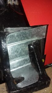
Also finished sorting out the new bracket for the fan belt cover. This will be bolted down by the same engine mounting bolt that attaches the grounding plate.
Saturday 10th Properly fitted the cylinder block drain tap. Doesn’t really look any different to the previous temporary fit photo.
Sunday 11th I have drilled the belt cover and it’s bracket to mark where the rivnut needs to be added. Would have done that tonight but the fittings and tool are at the boat ready to replace the missing nut when the hatch cover goes back on. Sprayed the bracket red to match the cover. Once the bracket is fitted and the control extension painted I think the engine is now ready to re-install.
Saturday 3rd March I spent some time in the garage re-assembling the engine water pump. Hopefully it wont leak as I didn’t replace the gaskets. Fairly easy to assemble using a ratchet set and extension shaft while on the bench but it wont be particularly easy to reach to solve problems once the engine is re-installed because it is the opposite end of the engine to the access hatch and the bolts will require a ring spanner because the universal joint is fairly close and too large a diameter to get the socket set onto it. 
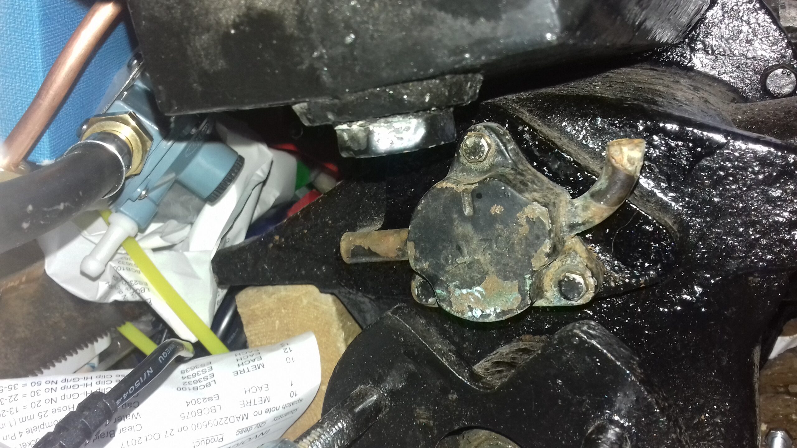
At some stage in the next couple of days I will spray paint it black and check it doesn’t leak using tap water. Nick from Vire UK doesn’t seem to like using silicone sealant on the water pump incase bits stick to the rubber or block the outlet so painting first seems logical as it may help ensure there are no leaks. Can paint the throttle linkage parts at the same time.
Final job on the engine itself is to fit the extra fan belt cover mounting and that needs me to get the rivnut crimping tool back from the boat. The rest of the pre-install work is to get the prop shaft bearings fitted and tidy up jobs in areas that will be inaccessible until the engine next comes out.