Wednesday 22/2/2017 Step one of the engine work was lifting it out of it’s space under the cabin access step and taking it home to the garage workbench where it stayed for 18 months as it gradually transformed and the boat systems were readied for it’s return.
On inspection and dismantling of the peripheral parts it was a good thing I had not tried to get the engine running in situ as there was q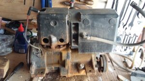 uite a bit of evidence of corrosion that will need to be dealt with. –
- Two of the zinc plugs in the cooling passages had corroded right through and a third was very thin. You couldn’t see that with the engine in the boat because the Dynastart covered them.
- I tried to blow through from the water pump outlet with no success – The inlet passage between the exhaust collector and cylinder was blocked (at least partially by silicone sealant used to re-assemble the engine at some previous restoration).
- The cylinder head cooling passages were almost full of rust flakes.
- Cooling water pump inlet was full of rust.
So far I don’t seem to have done any irreparable damage to gaskets during the dismantling.
With a little precautionary lubrication via the exhaust port there is

good compression left in the cylinder despite not having run for some time. The piston itself looks clean and turnover is smooth so I don’t think I need to dismantle the crank case or piston.
There is a slight concern for the crank bearing though as there is something like an oil reservoir cap which is very rusty suggesting something needs an oil supply.
I have accessed the shaft seal for the water pump and it looks OK but that is a major concern to the author of the Vire engine website  because any leak will damage the clutches due to water in the gearbox oil.
Thursday A bit more cleaning up of the engine and removed all of the Zinc plugs that close off the water galleries in the cylinder. These were originally designed to be made of Zinc to act as sacrificial protection for the other metal components and were intended to be replaced every few years. These ones had certainly been doing their job and the rings among the rust are all that is left.  So here comes the first of my re-design challenges – Nobody seems to do zinc plugs any more so I will have to replace them with steel and work out an alternative anti-corrosion strategy for the inside of the engine.
Having poked and blown out all of the rust flakes that I could remove, I then tried to get paint into the cylinder head. Did what I could with a brush then poured in about 50 ml and tried to tip it into all the corners inside. Quite a lot ended up leaking out of the various plug holes and entry & exit galleries. So I have painted the whole outside of the engine and gearbox starting with the excess paint. I dont really know how effectively the inside is coated or whether it may come off again once the engine gets hot.

<start of an on-going theme here> I have still not got the gearbox dipstick to unscrew even with the help of a plumbing spanner. Will try with the monkey wrench once the paint has dried (8 hours). However I do now know the oil is in reasonably good condition because the “oiling point” mentioned earlier leaked out quite a lot of oil when the engine was upside down – It is the gearbox breather.
All of the fuel system parts seem clean and functional with no bits found in float chamber or the fuel pump.  Fuel tubes have been replaced with the stainless steel braided tube. After trying all sorts of heavy duty cutting tools it turns out the easiest way to cut the braided tube is to use the cable cutters to get through the rubber tube then cut the braiding with ordinary scissors.
Removed the manual starting pulley (which I have also spray painted red mainly because we had a can left over from the camper van) so I could access the points and magneto. Points would open but not re-close so there was going to be a problem if I tried running the engine without looking at this first. Pivot was very stiff but eventually responded to a liberal spraying of WD40. Not sure if it moves quickly enough yet but an overnight soak should finish off the process of freeing it up.
Friday There don’t seem to be zinc core plugs available even from the engine dealer. Plenty of stainless steel or zinc plated steel versions from other suppliers but they will not provide any galvanic protection long term. I have been looking at the anodes available from MME group (www.mme-group.com) mainly because a web search showed they do a wide variety of shapes and sizes.
Possible alternatives would involve using the steel core plugs for the majority of positions and drilling & tapping one hole to take a screw in plug to which a zinc pencil anode is attached.
Saturday 25th The cylinder head design means that a full anode cannot fit inside any of the freeze plug positions as there is only 4 cm of available space before the anode would be in contact with the cylinder wall.
The approximate dimensions suggest the smaller size plug hole could be tapped to a 1” thread to take the largest of the MME brass mounting plugs. Slight difficulty is that the tap to fit the commercial anode mount (1” npt) costs around £110 so I might have to find a tool rental company with one or else identify a different mounting method. Need to check the feasibility but Car builder solutions sell a M22 brass fitting for “soldering” into radiator systems, that has a 25mm rim which might braze or silver solder into the core plug hole. There are then a series of adapters which could be re-drilled and tapped to accept the smaller anode mounting plugs
The other possibility would be to put an anode in using the blanking plug opposite the link between the cylinder head and the exhaust collector. I will take that out tomorrow and see whether an anode could reasonably go in there. May not be ideal as it would be out of the water if the engine was partially drained whereas one at the bottom of the casting would still be protecting it. Would also probably have to take off the exhaust collector to check and change the anode.
Sunday I have decided that adding a bolt in insert inside the cylinder head is impractical because there are internal webs in the casting which go right up to the inside edge of the plug hole. Brazing or silver soldering onto the outside are both theoretically possible but from the internet posts do not seem likely to work without completely dismantling the engine and involving someone with a lot of equipment and experience doing that sort of work on cast iron.
Managed to get the top plug out of the casting. A 7.5 mm drill shank just fits through the (rusty) hole and goes quite a distance into the head. Plug is 0.543” across the threads (13.8 mm so presumably a M14 fitting). May be practical to drill out the inner hole to 11 mm and then put a 10 mm anode through using a 14 mm brass blanking plug with a hexagon head. Should be reasonably easy to get that particular part as it is a fairly standard oil sump plug (VW Beetle & camper, Vintage Mini etc) and they cant all be using steel plugs and allen keys to put the fitting in and out.
Wednesday Bought a digital calliper set on the way home from work so I can accurately measure the diameter of the plug holes and the steel blanking plug. Then I can finally work out whether it is practical to put the anodes in at the bottom of the cylinder head casting or I have to go for drilling out the access point at the top.
Saturday Tidied up the exhaust collector face which mates with the cylinder head. This has two places where water passages pass through the gasket -.
- The inlet fitting screws into the exhaust collector casting but water then goes straight into the cylinder head casting. This side had obviously been “tidied up” at some stage because there was a plastic tube glued into the passage. Looks rather as if this was 3/8” OD and glued into place with something that looks a bit like plastic padding. As the tube was buckled there was a lot less than the expected internal diameter available to carry water and it may even have been completely blocked. That passage is now drilled out to 11mm and I will do a similar lining job but ensuring the whole bore is available for water flow.
- The return flow from the cylinder head should have a rubber “gasket” according to the Vire handbook and the various web resources. This one had 3 different diameter O rings stacked between the two surfaces. Seal recess is 20.33 mm diameter and 4.55 mm deep (both slightly more if you allow for the fact that I have painted this part). Gasket has a hole 19.7 mm diameter and is 1.33 mm thick so my estimate for the original rubber seal dimensions is something like 6 mm thick and 20 mm OD. Should be able to find something reasonably similar but I will also follow the previous plan as the two areas had the additional help of silicone sealant to ensure the channels were leak free. Plastic inlet elbow was also fitted with silicone.
Still fighting unsuccessfully with the gearbox dipstick. It is corroded in very solidly and wont even shift with the monkey wrench, just shave off more and more aluminium. Also tried making a tool to act as a lever to turn it using steel rod through the hole. Made it from 2mm wall thickness mild steel tubing but only managed to tear the tabs which should have applied the force to the aluminium part. So back to plan A and a bit more hammering to try to loosen it and general soaking with WD40.
Researching the core plug options –
- Steel ones from the official UK dealer. Core plug set for Vire 12 (NB Galvanised steel so poor galvanic protection but last longer than plain steel) £12.30 http://www.ebay.co.uk/itm/VIRE-12-core-plug-set-5-NEW-BZP-finish-/230409876815
He also has the pump impeller (£24.00 http://www.ebay.co.uk/itm/VIRE-7-12-IMPELLOR-UPRATED-/230805206165 ) and magneto points (£22.00 http://www.ebay.co.uk/itm/VIRE-6-7-12-points-contact-set-OEM-bosch-platinum-tips-1-set-QA-mirror-finish/230456440715?_trksid=p2047675.c100005.m1851&_trkparms=aid%3D222007%26algo%3DSIC.MBE%26ao%3D2%26asc%3D41415%26meid%3Da5e5c71f4ad040edae99aa86572df1ce%26pid%3D100005%26rk%3D3%26rkt%3D3%26sd%3D230409876815) - A UK manufacturer stockist offers a choice of mild steel or stainless steel plugs of the right diameters. Either will be OK if there is independent galvanic protection as will be needed for the official ones too. – Need 1 25 mm (OD £1.05 http://www.coreplugs.co.uk/index.php?route=product/product&path=74_59&product_id=113 ) and 4 30 mm OD (£ 1.13 http://www.coreplugs.co.uk/index.php?route=product/product&path=74_59&product_id=118) . Total cost for mild steel plugs – £5.57. + P&P comes to £6. – Also sell sealant etc to help with installation. Ordered the core plugs from here!
To do the alternative anodes I will need a brass plug to replace the steel one at the top of the cylinder head and take the Zinc anodes. The 10 mm x 10 mm one will have a diagonal just over 14 mm so will need filing on the four edges to get it to fit (will be 14.14mm but has to go inside the female fitting’s threads therefore about one mm off each edge). –
- Parts for this were from Green sparkplug co ( http://www.ebay.co.uk/itm/B2-00592-M14-X-1-5-Metric-Male-Thread-Hex-Plug-Brass-/321673636573 £2.24 ), a Dowty washer or a copper washer to seal the plug to cylinder head.
Sunday 5/3/17 Started off the day with some more research –
From www.rdgtools.co.uk
- M 14 x 1.5 tap set ref 594907 (£12.00 inc VAT https://www.rdgtools.co.uk/acatalog/14MM-x-1.5-METRIC-TAP-SET-594907.html)
- ¼” whitworth tap ref 467 (£ 9.50 inc VAT https://www.rdgtools.co.uk/acatalog/1-4–TAPS-SET-BSW-x-20tpi-467.html)
- ¼” whitworth carbon die ref 468 (£8.50 inc VAT https://www.rdgtools.co.uk/acatalog/1-4–SPLIT-DIE–BSW-x-20tpi-468.html#SID=521)
With that collection I would also be able to prepare the thread to mount a second or third anode made from the offcut removed from the first one.
Phase 1 of the engine galvanic protection project – Brand new 12 mm carbide coated drill made very light work of drilling out the “cast iron” behind the access plug mainly because there was no cast iron, it was all rust and reduced to powder as soon as the drill came anywhere near it. From the position of the plug it would be possible to put in a zinc that went right to the far wall of the cylinder head cooling space. In practice it will have to be limited by the length of the available space in the exhaust collector as ideally I will need to be able to change it without having to remove the latter. Likely also means I don’t need the M14 tapping set so the RDG tools order will only be for £18.
Tuesday Ordered the remaining bits tonight but the brass plugs seem to be not available in the regular shop and had to be ordered from their e-bay shop.
Steel freeze plugs arrived today so I should be able to get those installed soon.
Wednesday Freeze plugs went in easily. Line up –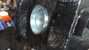
and then use a socket as a spacer while gently tapping the plug into place.
Finish off by tapping the rim down until it is flush with the casting all round.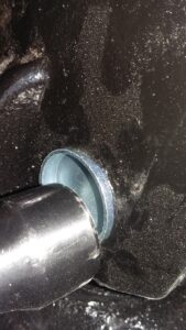
Only needed to fit three of the five because I think the other two are still the zinc ones and they sound fairly thick when you tap on them. I didn’t use any sealing compound but they just need a coat of paint to ensure any small defects in the casting don’t cause a leak. Frankly I dont think sealant is a good idea as galvanic protection will require an electrical connection with the Zinc anode and that has to go via the engine block. That is also why I am going with a copper washer between the brass plug and cylinder block.
Once the boat is launched the two remaining large plugs can be on board as spares and would be easy enough to fit if the existing ones start to leak.
On the starboard side of the engine block there is a brass drain valve screwed into a cast iron adapter. I have had a bit of a fight with the broken off valve connection which is absolutely not moving with either a centre punch or a sawn off hex key as drivers. Will try to find the proper stud extractors over the next couple of days but it may be easiest to work out what thread the adapter fits in the block and start again.
Monday 20/3/17 Assembled the dynastart back onto the engine as all the remaining bits of work are on the other side of the cylinder block.
Ordered a couple of fan belts from www.beltingonline.com, seems likely that the SPZ800 will be suitable and at £2.11 each it would make sense to have a spare aboard.
Tapped out the mounting bracket on the dynatart (was likely an M8 thread originally as it was rust rather than metal that was removed) and bought steel strip 16 mm wide & 2 mm thick to make an adjustment strap as I have not seen anything even vaguely like one among the bits loose in the boat.
Once I have found the original drive belt in the garage or received the ones ordered today I will be able to get the engine turning over under battery power to check and adjust the magneto, points and spark gap. Apart from fitting the zinc anode and a new pump impeller, the engine and it’s electrics board will then be ready to go back into the boat.
The cooling water supply, fuel tubing and prop shaft work would be easier if they were done before the engine is re-installed because they all need access close to the engine. Similarly access to the anode mounting bolts will be easier if I don’t have to crawl round the engine so at least an anode to engine ground connection needs to be in place.
Thursday 23/3/17 Put the belt on the engine and connected up the electrical system but it seems the dynastart has a problem. It wont start from any position in about half the rotation. Turns the engine over 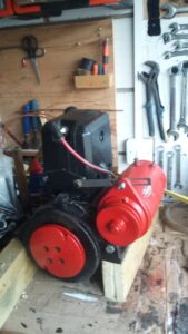 reasonably though once it is running but needs looking at. So I took it off the engine and tried to start to dismantle it. The long bolts through it are losing their corners because It doesn’t seem to be exactly 10mm across flats so didn’t get far with that and will have to use the bolt & nut removal tools on that when I finally buy them.
Might be something simpler like a brush problem, but my suspicion is that one of the armature coils may have failed so I may be in the market for a replacement, getting a rewind done or revising the system with a separate starter motor and charging system (Have subsequently found there is a company in Chesterfield which does Dynastart repairs www.vehicle-electrical-rewinds.co.uk).
Also no obvious spark while the engine was turning over however there is currently no control switch wired in and I don’t know whether the stop/run switch is across the points (ie closed contacts = stop) or is grounding one end of the coils to make the ignition work (ie closed contacts = run). May well be the latter if aircraft magneto ignition systems are the same so it is entirely possible that I shouldn’t have been expecting a spark.
Saturday 1/4/17 Managed to get the bolts out of the dynastart. One of the brushes was stuck so that might not have been helping with the “starter motor” function of the device.
Sunday Over night I ordered a proper starting battery (http://www.eurocarparts.com/ecp/p/car-parts/car-electrics-and-car-lighting/electrical/car-battery/?444770631&1&cc5_993). The sealed gel ones are OK for low to medium current use such as lighting and bilge pumps but the starter really needs an appropriately designed battery to be able to deliver the required current. The one I have ordered on click & collect will deliver around 300A for a short period. Now that I know dimensions (175 x 175 x 212 mm) I can sort out a suitable battery box.
Collected the battery from euro carparts during the day. Put it on charge when I got home so it stands a chance of getting the engine to go over compression.
Then temporarily connected up the engine electrical board and fitted the cables to the new battery. Not only turns the engine over more briskly than the gel batteries could without the spark plug in position but also with it in place.
Saturday 6th May Now have a shield to protect people from the dynastart drive belt. Bent up from 0.6mm steel plate. Started off from a measured plan but ended up snipping off bits to ensure it sits reasonably close to the flywheel without obstructing the pull starting pulley.
Also acts as a mounting for the local “run” switch. Tidied up the wiring a bit while fitting it as the original 4 way connecter block was seized up solid and there was no alternative but to replace it with a modern chock block connecter. Not ideal as I don’t trust them in damp conditions but I will try to water proof it by spraying the whole thing with lacquer once all the connections are done.
Outcome of the magneto testing is not encouraging. No spark although the contact switch is working. At the moment the problem could be almost anything. Managed to get the nut off the end of the crank shaft and have applied WD40 and my 3 point gear puller (A claw and plate based version) but the flywheel has not yet budged. I have tightened the puller as much as I can and am leaving it under tension overnight. Maybe the WD40 will soak in gradually and it will come off tomorrow.
Sunday 7/5/17 Managed to get about another quarter turn on the puller before we went out but I don’t think that was due to movement, just longer handles to the spanners.
Saturday 13/5/17 Didn’t get anywhere with the flywheel removal but I did finally get to try out the nut removal tools. The original set was much too small but the largest one in the newer set was just the right size. As the dipstick is made of aluminium it hammered on fairly easily with the lump hammer. Had to use a G clamp to hold the engine down on the wooden bearer and another one to stop the engine and bearer from rotating on the bench but with that arrangement in place the torque wrench shifted the stuck thread fairly easily.
In the photo the dipstick looks OK as if it had a nice clean thread. In reality there is almost no depth at all to the lines which look like a thread, it is only just deep enough to have a rough try at measuring the pitch of the thread. Both the dipstick and the gearbox casing will need their threads tidying up because a lot of aluminium (or oxide) seems to be still embedded in the gearbox thread. So the next tool order will include a 20mm diameter 1.25 mm pitch tap and matching die.
I have now tidied up the somewhat mangled external bit with a file. As you can see from the photo, there is nothing left of the larger diameter knob which should have provided a limit to how far the dipstick can screw into the gearbox.
That was a major piece of progress so now I can change the gearbox oil. Once the magneto is looked at and the cooling pump impeller replaced the engine can be re-assembled and go back into the boat. Doing that will require me to be finished with the work aft of the engine bed and also to have worked out what bolt and nut threads are involved in the engine mounts.
Sunday Fitted rivnuts to the fanbelt cover fixing bracket.
Monday From the thread count and approximate diameter of the engine side of the anti-vibration mountings I think the stud is 3/8” UNF (should be 24 TPI and 9.53 mm diameter. I measured it at 1.049mm pitch and 9.77 to 9.83 mm dia). The thread count matches exactly and the diameter is a bit larger but not sufficiently so to be the next size up on any standard thread pattern. So I think a little cleaning up of the rust will give a good fit.
The mounting bolts which were present are all slightly corroded sawn off mild steel M12 bolts and, when tightened with a spanner, they fit the threads so I think that is correct. However I am not absolutely sure they actually fitted the threads in the metal engine mounting structure as none of them were fully screwed in when I removed the engine. Seems like a check is needed with a new stainless bolt and, as I have the required size of metric tap, maybe a little bit of persuading for the surrounding fibreglass cladding.
Wednesday The size of the holes for engine mounting rubbers is less than 12mm as I suspected but is larger than the 10 mm bolts that I tried previously so there is a choice between tapping the holes out to 12mm or trying to work out what the existing thread is and obtaining suitable bolts.
Saturday 20/5/17 I had another go at pulling off the flywheel. This time with more lubrication on the puller threads. Initially seemed as if something was giving as it was tightening better than previous attempts. 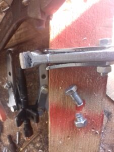
I didn’t notice in time but it was one of the bolts in the puller that was giving rather than the flywheel moving.
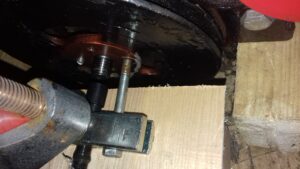 Saturday 5/8/17 On to plan B with a different type of puller that bolts into the flywheel. – Rearranged the workbench a bit so I could turn the engine round. That meant I could use a clamp to hold the new puller and tighten the central bolt with a spanner and extension tube. A good idea and it meant I could get more force on the flywheel however the result had more in common with destructive testing than dismantling. One of the bolts appears to have had a flaw in it’s core so it stretched and broke off.
Tuesday – Managed to wreck two more bolts while trying to get the flywheel to come off. While using the torque wrench to help tighten the removal thread I noticed that the second of the original bolts had started to stretch so I changed to using a new one bought for the trailer. Might as well be made of engineering grade cheese for all the use they were as the thread stripped even with two nuts to spread the load. I think I need to get a couple of high tensile bolts before I will be able to get that flywheel to come off.
Wednesday – Tonight I have been learning about the bolt tensile strength classifications. Both of the “engineering cheese” bolts had no markings on the head so will most likely be the low grade 4.6 steel which breaks at over 4 x 100 newton per square mm and starts to stretch permanently at 60% of it’s breaking load. Could even be a lower strength than that as you don’t really know with un-marked bolts.
Really need 10.9 or 12.9 grade as I would be able to get up to 5 times the force on the flywheel. Even 8.8 would be better than the ones I already broke and probably easier to find and more affordable than the really good ones. At the moment I seem only to be finding places which sell them in packs of 100 or 200 so I would be dealing with a £150 bill and only want 2 of them. I am going to try the farming shop in Tickhill on Saturday to see if they have anything small enough of a suitable grade.
Saturday 12/9/2017 – Got two grade 8.8 bolts for under a pound each. Made all the difference and the flywheel came off reasonably easily.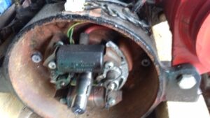
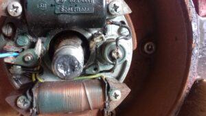
Now adjusted the points to 17 thou and have identified that the low voltage side of the system appears to work – By leaving out the key I can put the flywheel on the shaft and spin it by hand which produces a spark at the points at least some of the time. Tried to polish up the points and now don’t seem to get the spark any more so will have to try a bit more cleaning. Not sure but it may mean I need to order some replacement points. The vire engines website has the simpler parts of the ignition system available along with links to several useful utube videos –
- points – https://www.youtube.com/watch?v=sT_IDcJYa84
point gap adjustment – https://www.youtube.com/watch?v=hH0v7BkbYu8 - ignition timing – https://www.youtube.com/watch?v=1wkV_id6PHk
- Static ignition coil testing – https://www.youtube.com/watch?v=DWDVredOTUo
- Diagnosing starting problems – https://www.youtube.com/watch?v=9J0fYHwJQus
- Fuel system diagnostics – https://www.youtube.com/watch?v=zTiEe4P7FQo
- Dynastart testing – https://www.youtube.com/watch?v=c0XSi3HH7No
- Points condition check – https://www.youtube.com/watch?v=8MFFs3FgBhU
- Changing the condenser – https://www.youtube.com/watch?v=AI25X6uqdrE
- Setting up Teleflex controls – https://www.youtube.com/watch?v=p2S3JT6EqnY
Replacement magneto coils seem to be a problem as they are £110 each and the minimum order is 4 presumably to discourage people from ordering them without consulting the engineer. Hopefully it will just be points and a condenser that I will need.
Unfortunately the decent test meter seems to be at the boat so will have to check the resistance of the HT side of the system later. Matthew has the ignition testers in his garage so I will collect those and try that later although I have my doubts about the HT lead as there is no sign of any wire or other conductor visible when you remove the spark plug cap.
Collected the meter from storage and on returning home the ignition system now seems to be creating a spark both at the points and the sparkplug all of the time. Not sure if it needed to dry out after being thoroughly sprayed with WD40 or whether the points are a bit sticky and don’t always close properly unless they are being “run” regularly. I think the order from vire engines will be for the pump impeller, a spare set of points and the fuel filter
After all that work to get it off, the flywheel is back on and the crankshaft nut tightened again. Still need to sort out the sealing arrangements for transfer of cooling water from the cylinder head to the exhaust resonator, replace the cooling water drain valve and make a replacement throttle operating lever before the engine can be declared ready to go back in the boat.