So, what do all of these have in common other than involving various diameters of pipes? In my case those pipes are all entirely or partially located inside the engine compartment and will be impossible or extremely difficult to work on after the engine has been re-installed. As the boat was received all three systems also had potentially significant issues which I realised were potentially dangerous. I know that the Boat Safety Scheme ( http://www.boatsafetyscheme.org ) strictly applies to boats on canals and rivers rather than sailing boats that go to sea however I am adopting the basic principles unless I can see an obvious reason why an alternative would be safer in my situation.
So lets start with the gas system. The original system was based on an LPG cylinder located in the port cockpit locker which is open to the sea through two holes in the transom. This was a “Camping gas” type cylinder fitted with an adapter to attach it to a marine type pressure regulator. The low pressure side was attached to copper pipe which was coiled to allow it to flex and which went down into the engine compartment, across under the cockpit floor then down under the water tank (on the starboard side) and emerged into the galley unit.
So what’s wrong with that ?
- The age of the components. You are supposed to regularly replace regulators as corrosion can cause them to leak or provide too high a pressure. Marine regulators like the one fitted are slightly more complex than an ordinary camping / barbecue version as they are two stage and have a safety vent to protect the second stage in the event of any problems with the first one. That prevents any over-pressure damaging other components located in more hazardous parts of the boat.
- Unsupported copper plumbing (coiled and directly attached to the regulator which will move when the cylinder is changed). There is a potential for the pipe to fracture due to fatigue and I dont know how old it is.
- There were two lengths of pipe joined by a compression fitting in the middle of the run across above the engine. Even without fatigue problems, I dont want a potential leak of a gas that is heavier than air to be located in the same enclosed space as the contact breaker points, hot exhaust system, spark plugs and starter motor brushes! Almost every potential source of ignition on the boat is in that space.
- Pipes through inaccessible spaces – I want to be able to visually inspect the whole pipe run.
- I also think the pipework needs to be grounded so any static electricity or stray wires will not cause sparks to potentially ignite leaking gas.
- No method of checking for leaks (apart from by smell / explosion caused by the above mentioned ignition sources).
- The aluminium “adapter” was corroded into the brass & steel cylinder so could not be un-screwed. Fortunately the valve on the adapter was working but I still have a potential bomb to disable somehow.
- No obvious stop tap at the galley end of the pipe although there could have been meant to be one and it wasnt still in the boat.
So the gas system needs to be replaced / upgraded.
I now have a marine type regulator (ie 2 stages with overload relief valve and dedicated vent pipe) located in the same “fuel” locker as before. The version I am using is bolted to the bulkhead and has a high pressure hose to link it to the gas bottle which avoids the issue with fatigue on copper pipe when the bottle needs regular changes.
The regulator is plumbed directly into a bubble indicator. With the  cylinder valve on and everything else turned off you can press a button and if there are any bubbles visible in the fluid then you have a gas leak after the checker! Check every time you turn on the gas and you will always be as safe as you can be.
From there the pipe goes round a 90 degree bend and through into the 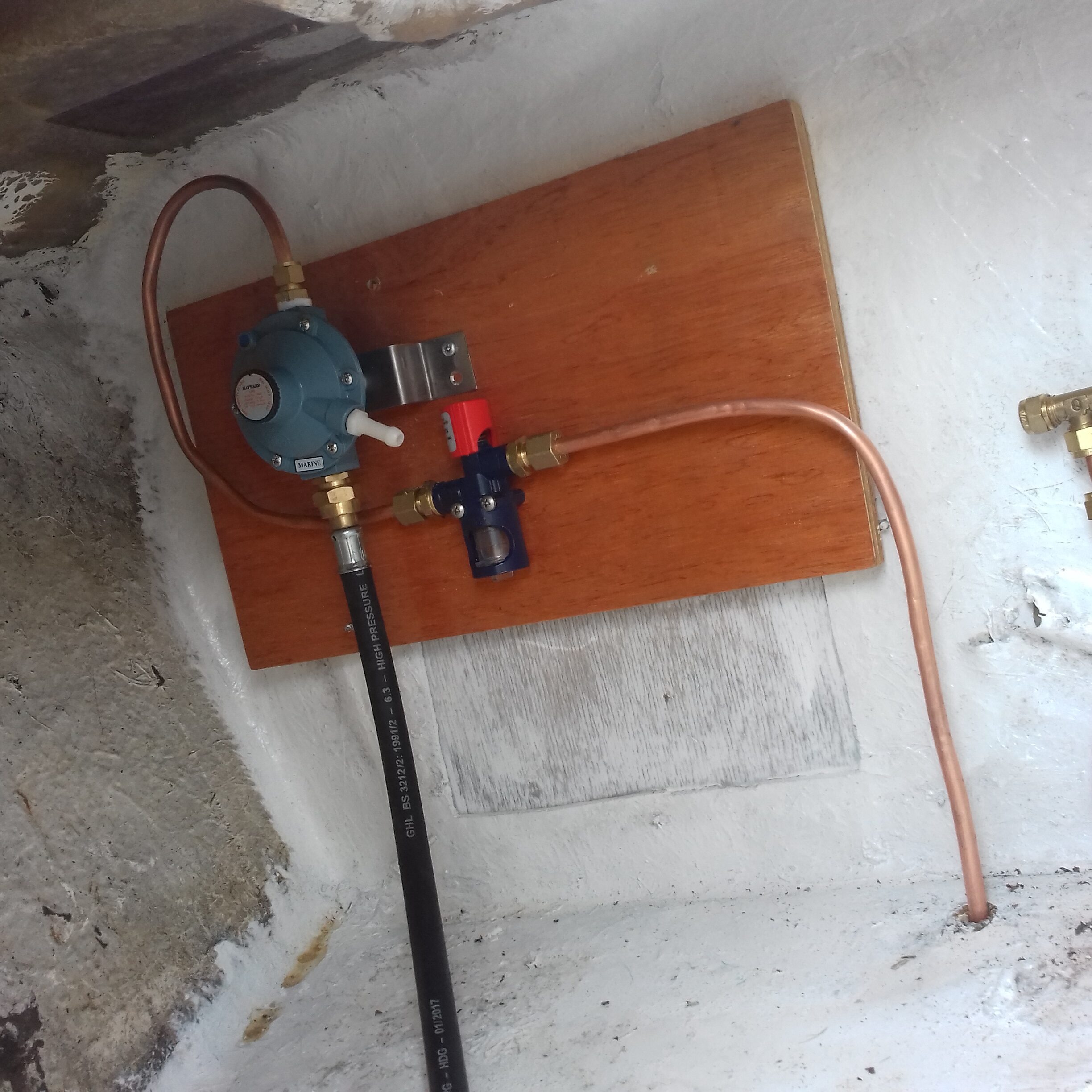 engine compartment. Now this is where I dont agree with the BSS manual as they would require me to have the gas pipe running through that space in a conduit which is sealed at both ends into the walls of the compartment. They are not happy with using any type of sealing compound on the pipe and want the ends of the conduit left open to the non engine spaces. That would be OK if the conduit didnt start in the fuel locker (which has to drain overboard at or near it’s lowest point) as their scheme would have the fuel locker ‘draining’ any gas or petrol vapour into the cabin. Effectively the engine compartment is open to the cabin anyway so there would be little or no benefit from a conduit even if it was sealed at the fuel locker end.
In the engine compartment I start with a 270 degree bend (stress relief 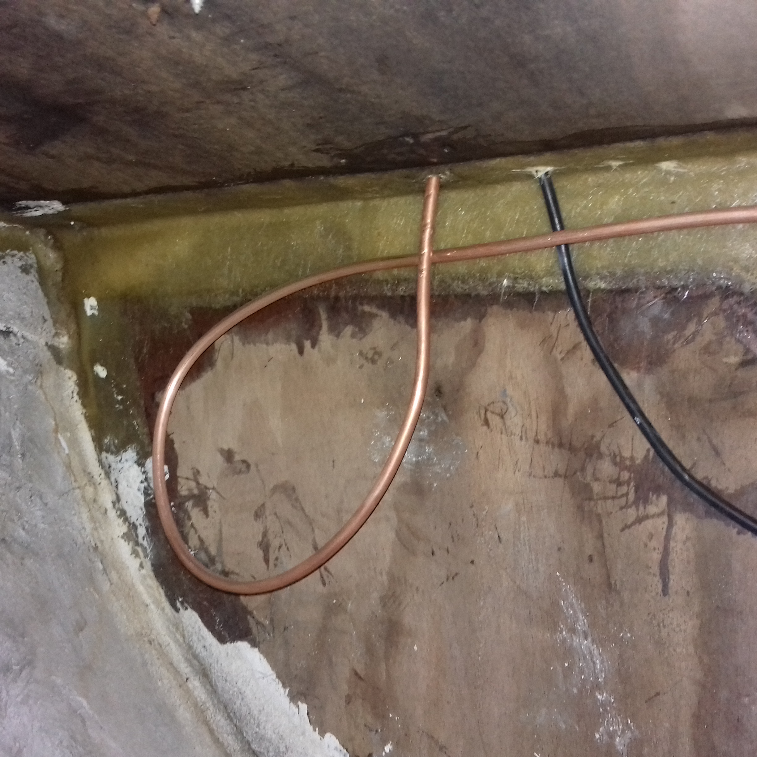 / expansion freedom and allignment with the bukhead to which it is attached) and then the pipe runs across the top of the compartment and out into the cabin. Then goes round the single bunk behind the insulation and into the galley unit where it is terminated with a ball valve before the connection to the cooker. All of the pipe run is supported using rubber covered aluminium P clips. From the bubble check to the stop valve this is a single piece of seamless copper pipe so there is no potential for leaks other than at the compression fittings.
The length of this plumbing system is small so installation of the part that was required prior to installing the engine only took one day to achieve.
As I am preparing this for uploading I am still waiting for the gimble fittings for my stove but the remaining plumbing will obviously need to be flexible hose. The cooker has flame failure devices so again is as safe as it can be.
Fuel for the engine – In the engine electrical section we already discussed the solenoid valve that is intended to prevent petrol flooding into the engine or engine bay and 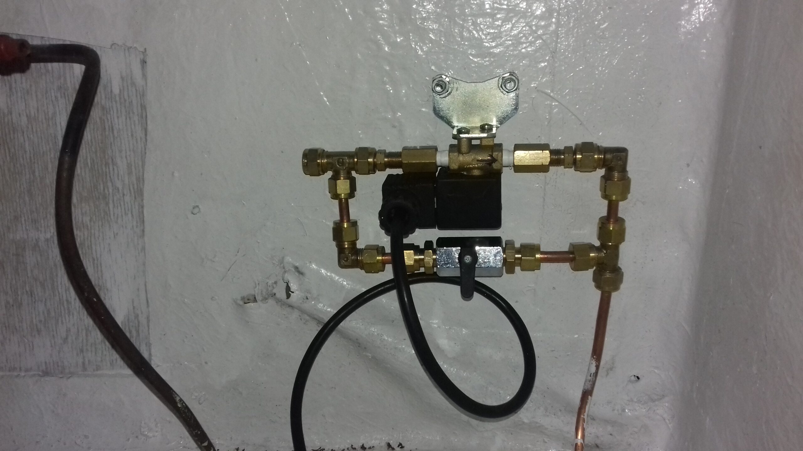 the original use of reinforced plastic tube. I also mentioned at the first investigation of the items that arrived in the boat that the original fuel tank had it’s base rusted away completely. That is probably inevitable for a metal tank given that the fuel locker is open to the sea water via the drainage holes which are only a few inches above the waterline.
The rest of the system is fairly conventional with copper tube to connect the solenoid valve and it’s manual bypass through to a filter and then into the fuel pump via stainless steel braided rubber tubes. 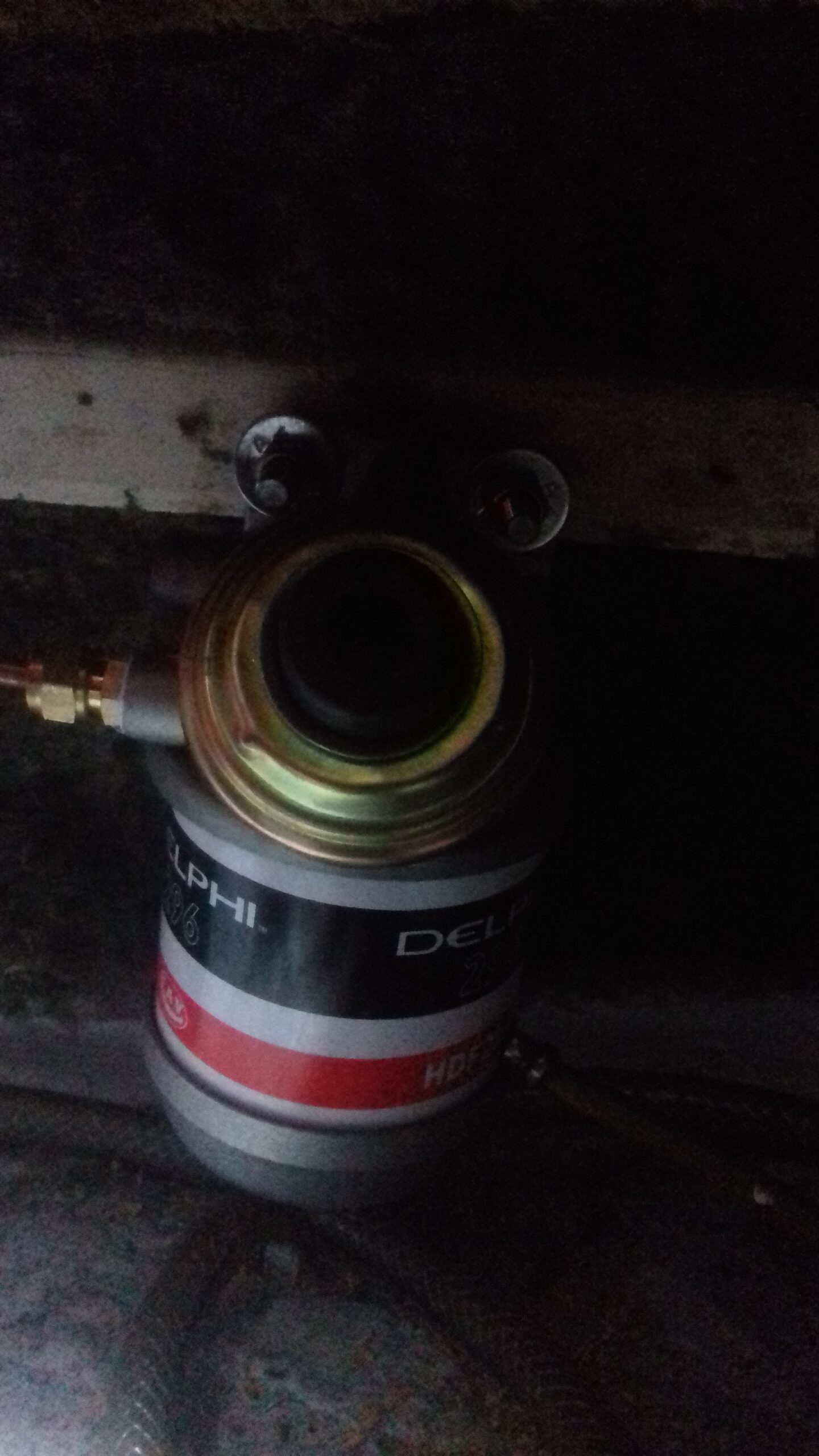 This is fed from a removable plastic tank coupled via plastic hose. All of these sections of the fuel system are easily accessible even with the engine in place and as with the gas system the parts nearest to the fuel locker are short runs of copper pipe and so were quickly installed.
The last section to the fuel pump is braided rubber tube again.
Engine cooling water (and all of the other through holes which were dealt with at the same time) is the section of this blog post that took the longest to sort out and is arguably much more important for the safety of the boat than either of the two fuel related systems. There was rather little of the system actually present in the boat and that was probably a consequence of the engine not having been operational in this boat.
The engine installation manual gives all the schematic that you need to install the cooling plumbing safely but there was quite a challenge actually delivering that. The key features are that
- The water inlet pipes must at some stage rise above the level of the waterline. Failure to achieve that can mean that there is a risk of water flowing either into the boat or into the engine. The former will potentially sink a boat in the event of any plumbing failure, the latter will wreck the engine itself via filling the wet exhaust system and the water flowing back into the cylinder.
- A syphon break valve is needed to prevent water from syphoning into the boat or engine when the level is below the waterline. This lets air into the system at the top of the flow path if the pressure becomes negative and limits the amount of water that can flow into the exhaust system when the pump stops to what is in the downwards pipes.
As with many of these plumbing jobs, the parts are available in corrosion resistant metals if you know what to search for on the internet but you always seem to need to purchase bits of the system from different suppliers as nobody seems to stock all of the parts you need. In the case of engine cooling I needed a through hull, ball valve, the anti-siphon valve, a T joint with the right threads to accept it and also three hose tails to match up to the diameters of the other fittings and hoses.
There was an inlet seacock which was already present on my boat however there was also a hole in the hull which appeared to have been possibly drilled to keep water from accumulating inside the boat. This was fairly close to the engine and blocking it with an inlet seacock would make the device much more accessible than using the original which is fairly far back in the compartment. Also the through hull and ball valve that worked with the drilled hole would be larger than the original so less easily blocked. The through hull fittings and ball valves are also a part of the anodic corrosion protection network and so details of selection and protection of these parts will be covered in that blog post.
The first hole through the hull to be brought under control was the new engine cooling inlet.
Sunday 29th April 2018 After eating tea , I had another try at tidying my workbench in the garage. Quite a few things had sneaked away to hide under the engine including a small hole saw which was still on the mandrel. As it was a few minutes before 7, I then set off for storage. The 25 mm hole saw didn’t get the hole large enough to put in the skin fitting at the first try. A few minutes spent bending saw teeth outwards gave a moderately convincing 26 mm hole saw with only a few missing teeth . Having enlarged the hole a bit I was then able to gently screw 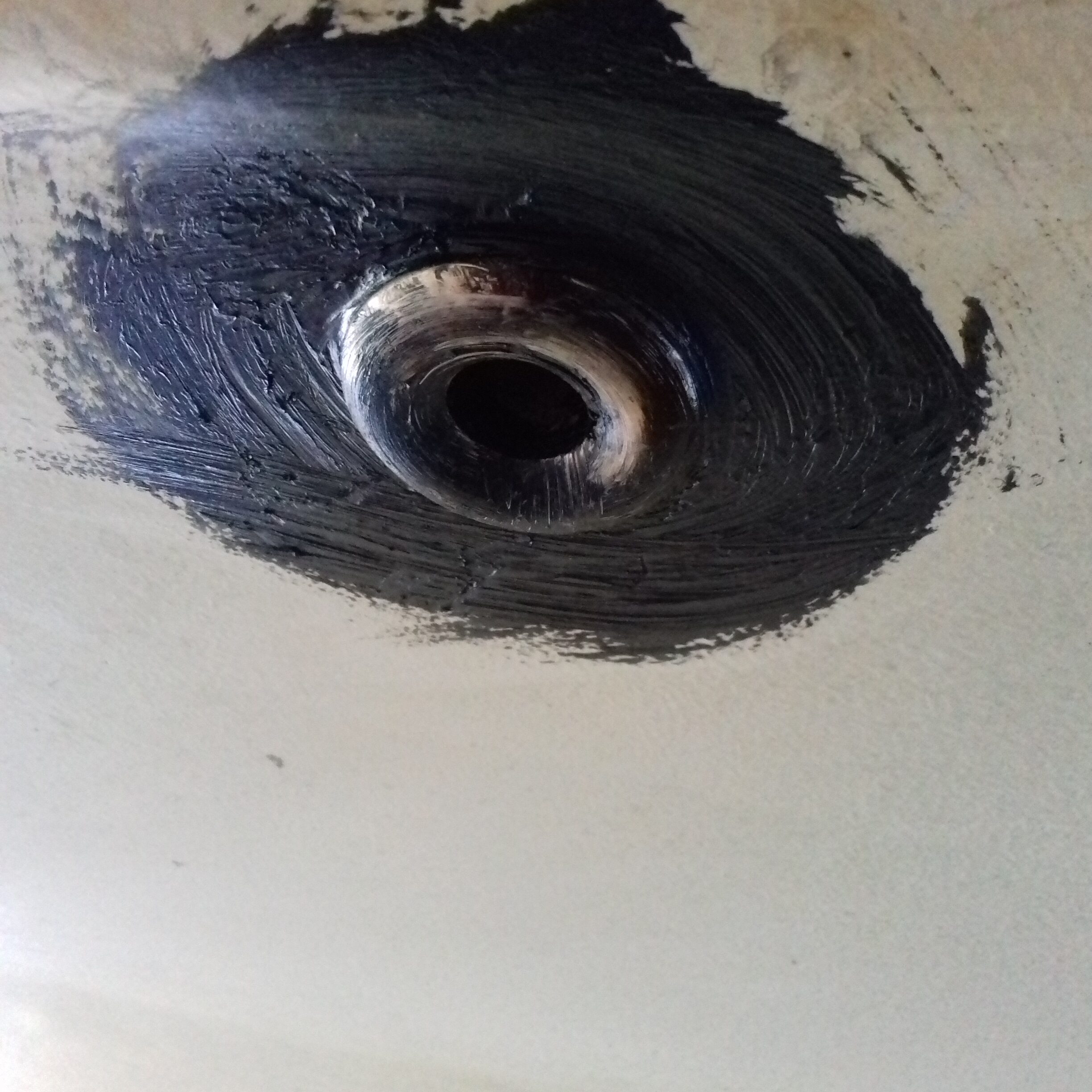
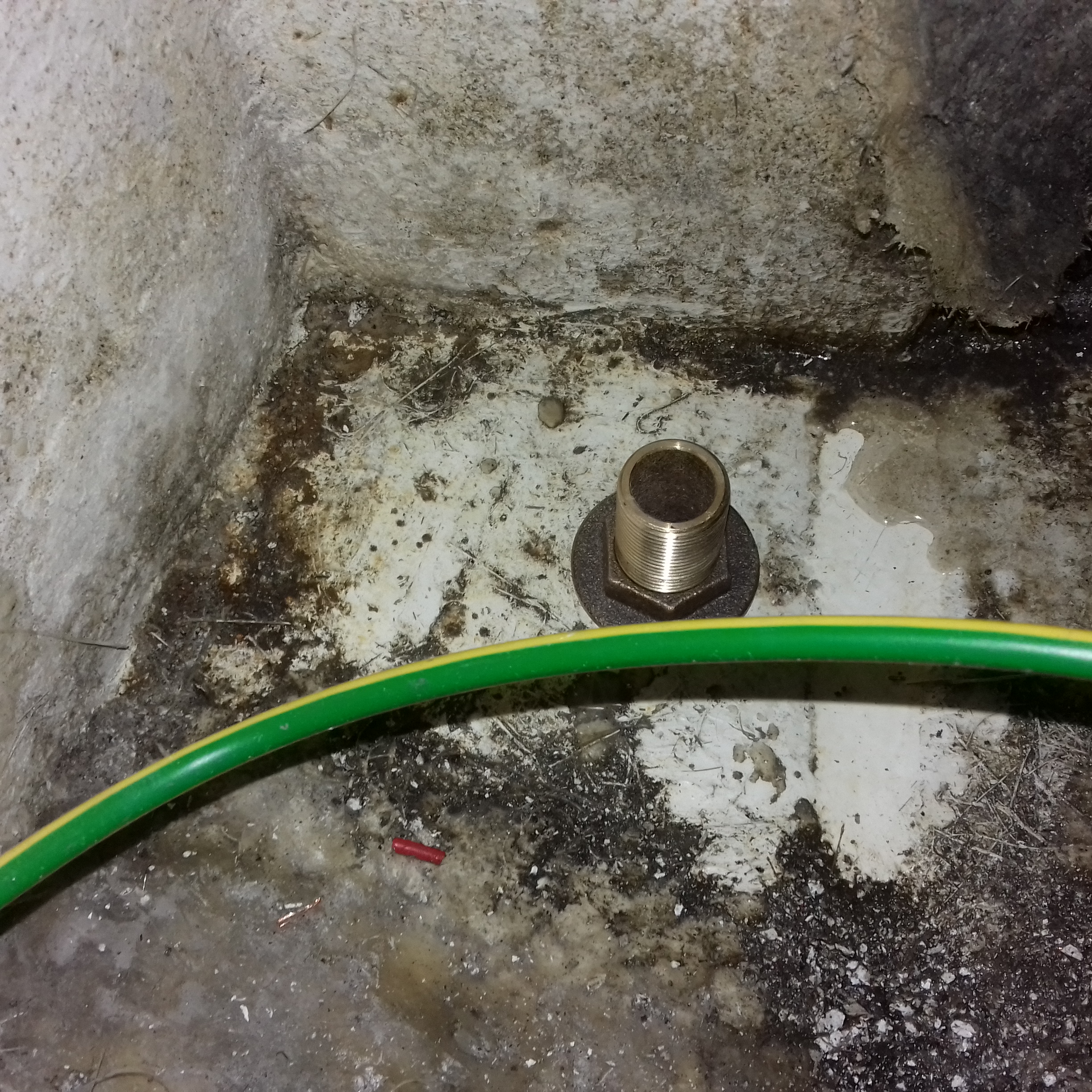
the skin fitting into the hull using an old screwdriver from the workshop at Matthew’s house. The Sikaflex sealant was not particularly keen on sticking to the antifouling at first but in the end I have a large ring of it extending an inch or so beyond the fitting on the outside and it seems to be well attached. The nut is on about as far as I can manage by hand but my largest adjustable spanner is a couple of mm too small to fit it properly. I will get a larger one so I can make a backing block, cover it in sealant and then do the nut up against a washer before attaching the seacock.
The nut is definitely in a wet and very mucky place being the lowest point in the engine bay
16th May 2018 Spent some more time trying to loosen the skin fitting for the galley drain. They definitely didnt mean this to leak, work loose or even be deliberately removable. Plan B is to buy a 1″ twist drill and remove enough metal and fiberglass to allow the new fitting to go in.
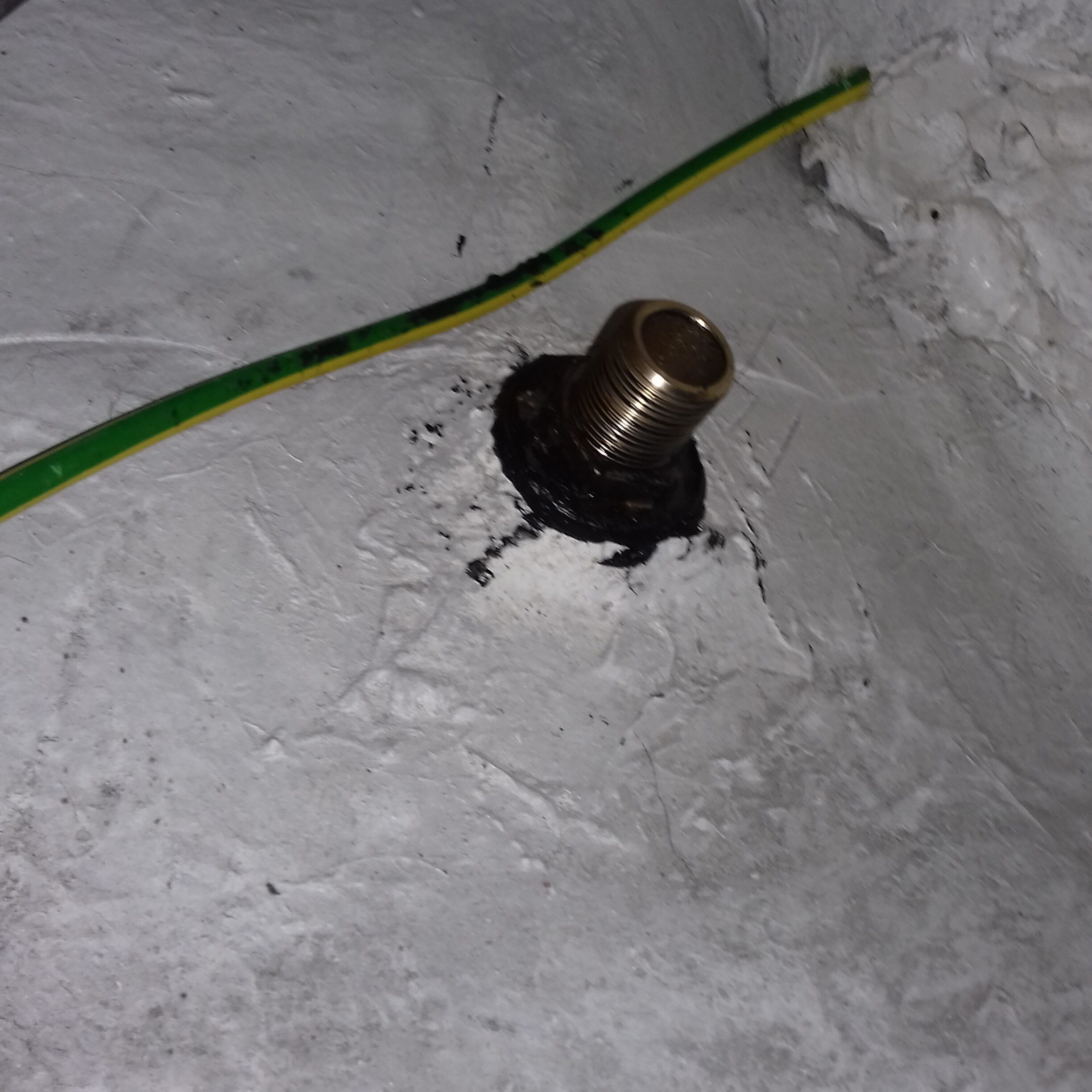
17th May Doesn’t look like much but the photo is somewhat of a milestone. Having collected the blacksmith drill bit yesterday I went to 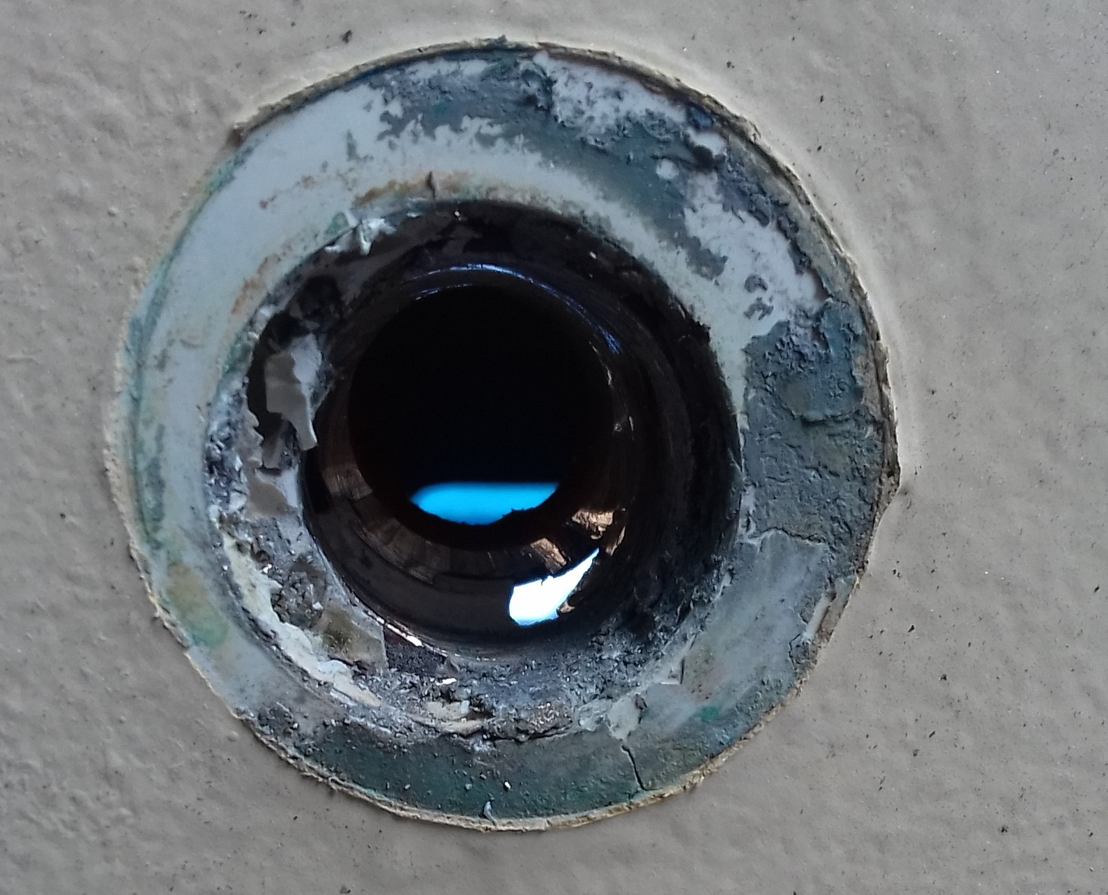 storage first thing and managed to drill out the skin fitting before heading off to work. 35 minutes driving and 10 minutes drilling but it means that I am about to have two controllable, watertight through hull holes. The drill didn’t go through particularly centrally so there is a full diameter piece still attached via a fragment of bronze at one side but that should shift with a little force. Then a little hull surface prep, a good smear of sealant, backing block and tightening the inside nut and I am on to plumbing in the sink and cooling water systems with reliable fittings.
9th June 2018 Tightening the new skin fitting in the bottom of the hull. Also fitted and tightened the galley waste skin fitting but couldn’t 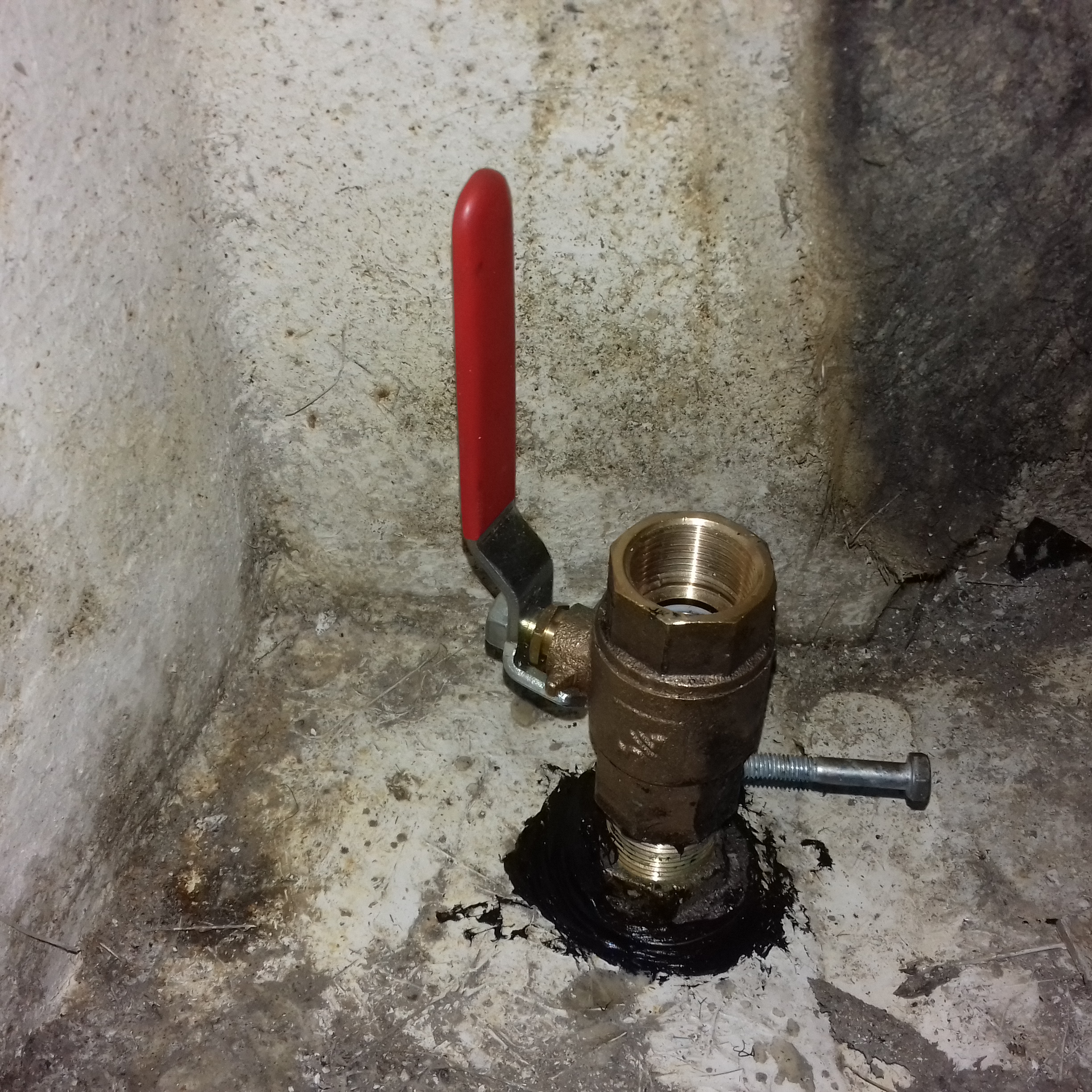
 fit the seacock because I had left it on the workbench in the garage. So that was significant progress with two out of the 6 through hull holes that I have to sort out.
Next on to try to sort out the blakes type seacocks that are jammed open. The classic solution to this problem is to put a metal rod in from the outside and hit it with a hammer to free the cone from the body.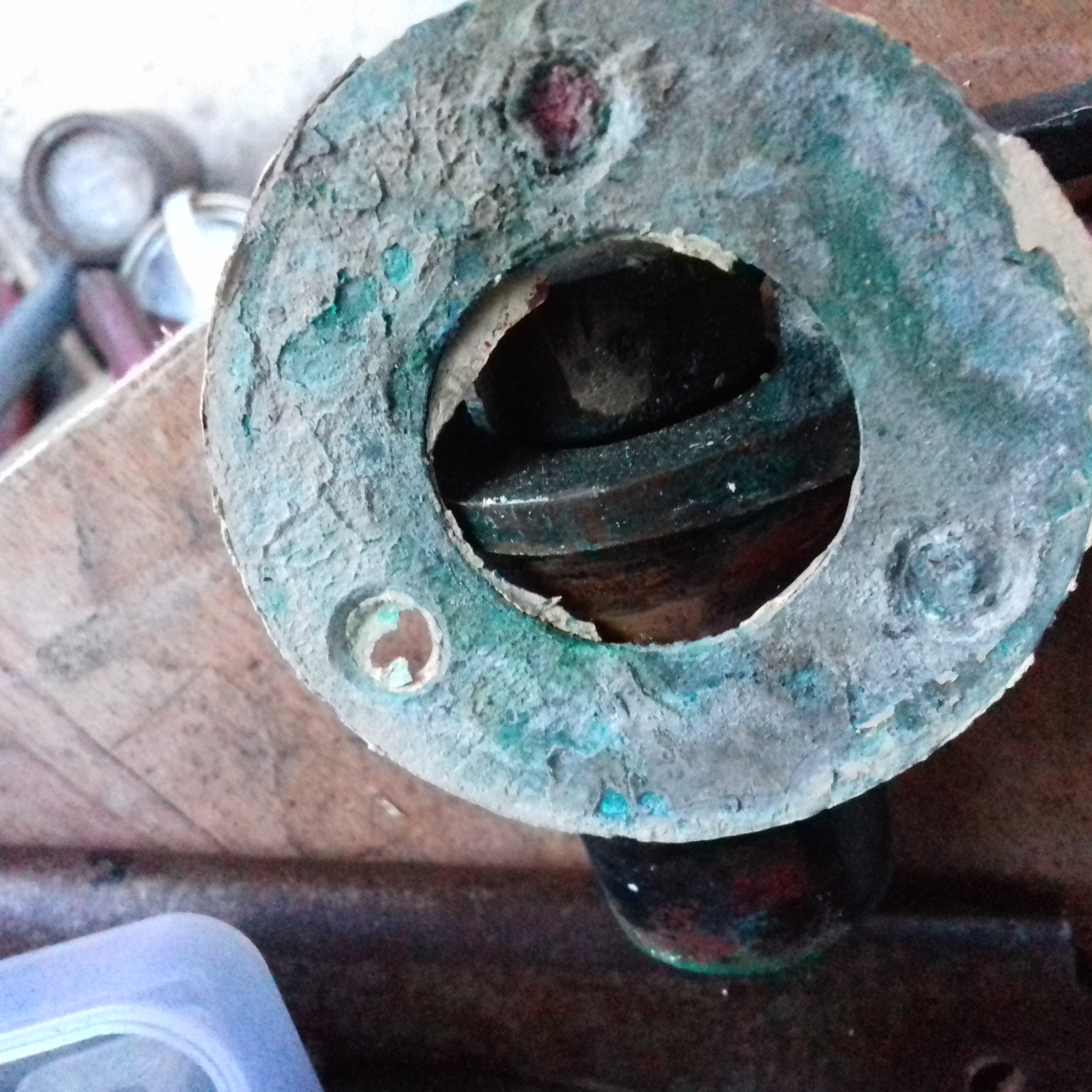
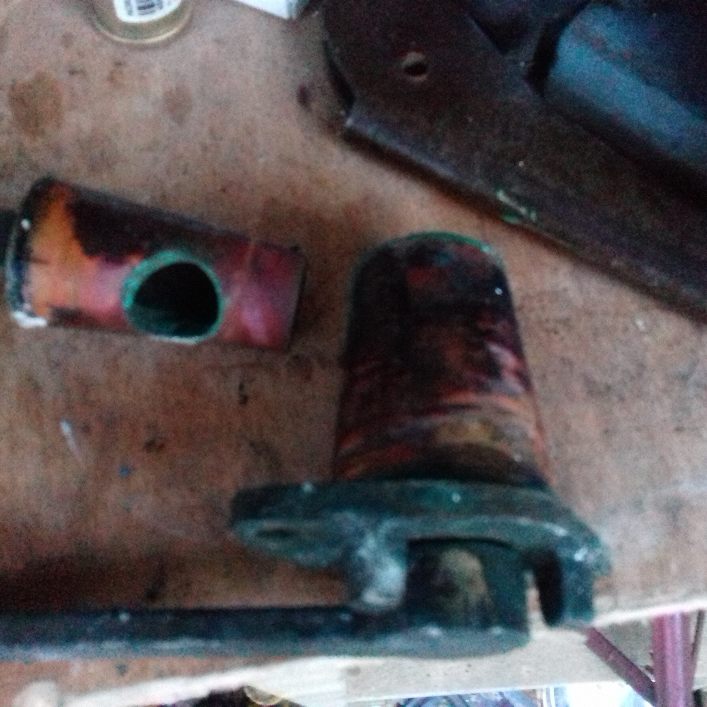
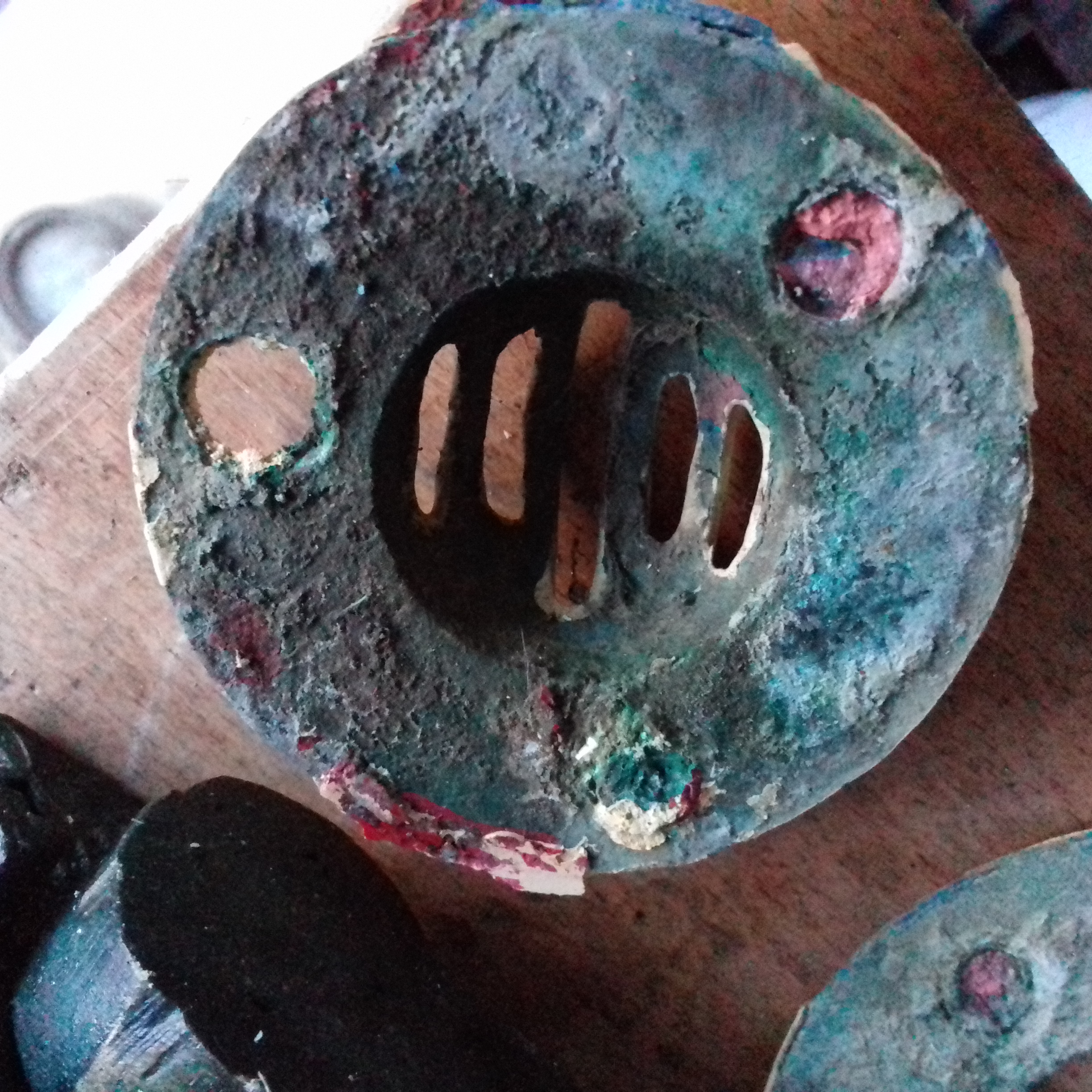
Worked quite well with both of them but the first hammer blow in each case revealed the consequences of decades of sea water on bronze (or was it brass?) without proper galvanic protection. Both of
the outside mounting rings fell off leaving clear indications why the term carroty is applied to unprotected fittings after a while. – Very clearly only copper left to give that colour where the screw heads broke off but more of that in the galvanic protection post.
Will definitely have to drill out the remains of the bolts and probably best to remove the entire valves and re-bed using new sealant and bronze bolts. The valves and their replacement bolts will be connected to the galvanic grounding network so the new bolts should last longer.
The valve cores obviously need a bit of TLC with grinding paste and grease to get them to be a good fit and movable on demand. Mounting plates also need a good cleanup before going back onto the hull.
Sunday 17th June Set off to storage and arrived there a few minutes after 8:00pm. Only at storage for an hour but got several jobs done or started.-
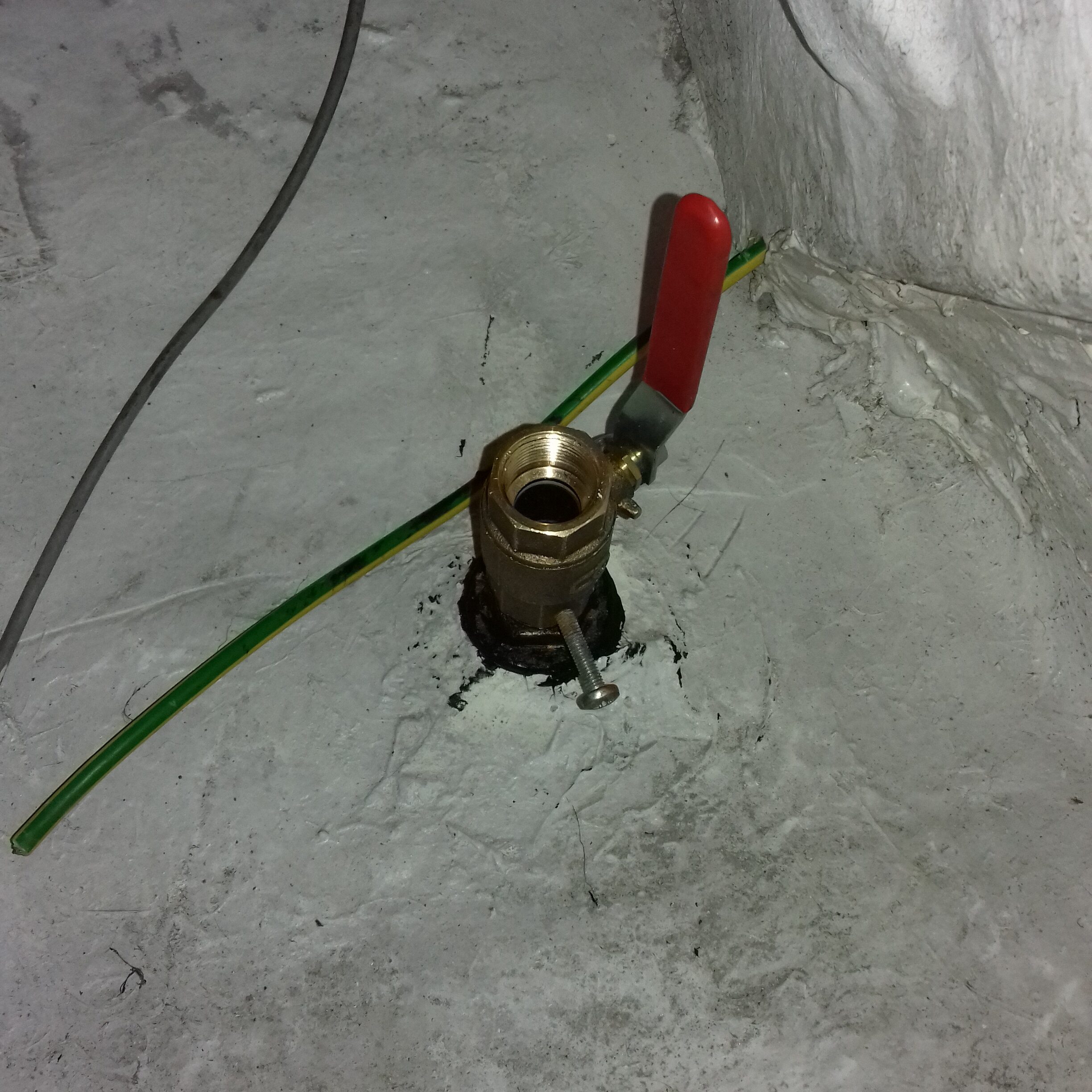
- Seacock attached to the galley waste skin fitting and installed an electrical grounding bolt ready for the next stage of that network install.
- Ground the cone parts of the two Blakes’ type seacock fittings. Took a few minutes for each part to do two sessions with the coarse mixture followed by one with the fine and then a good clean-up using kitchen roll.
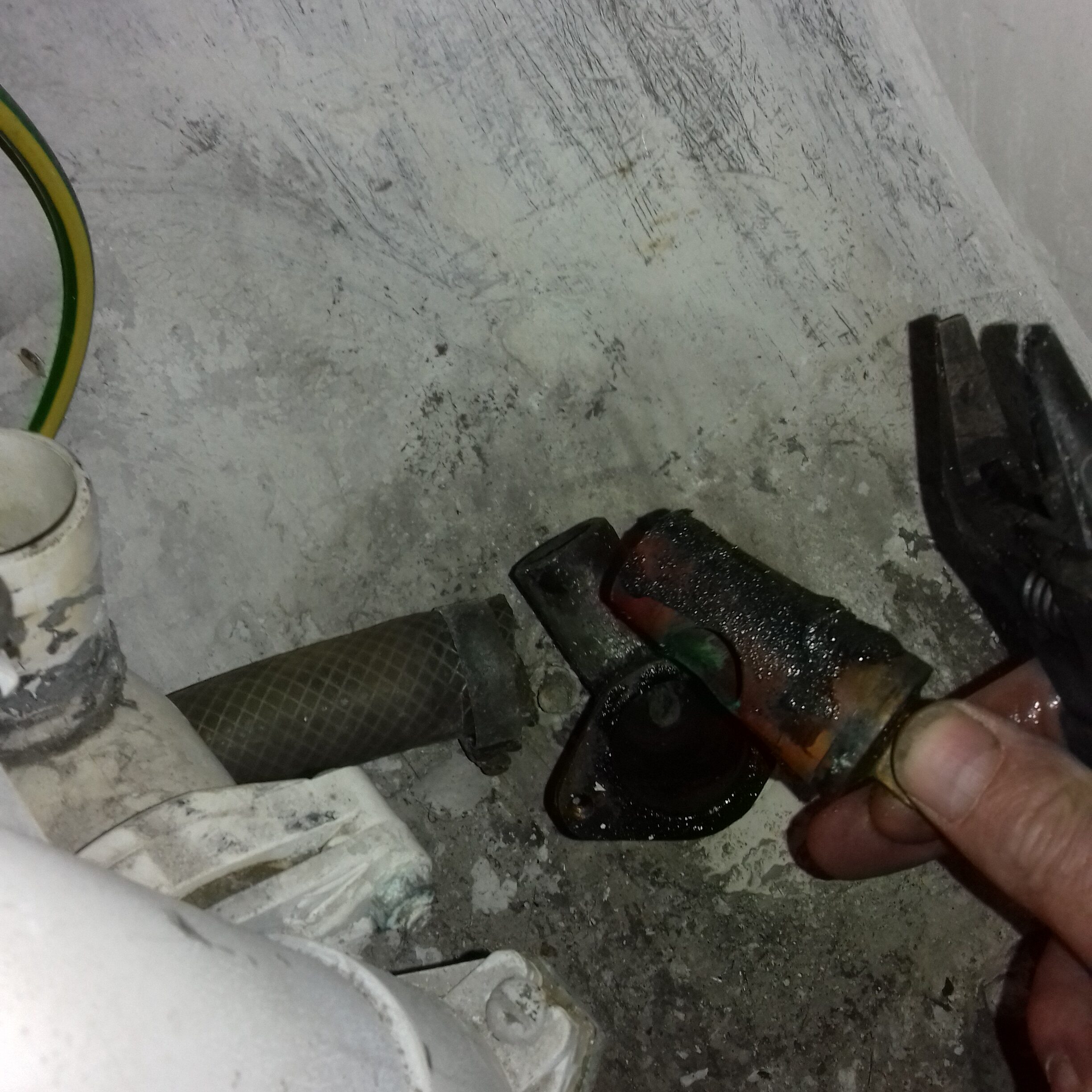
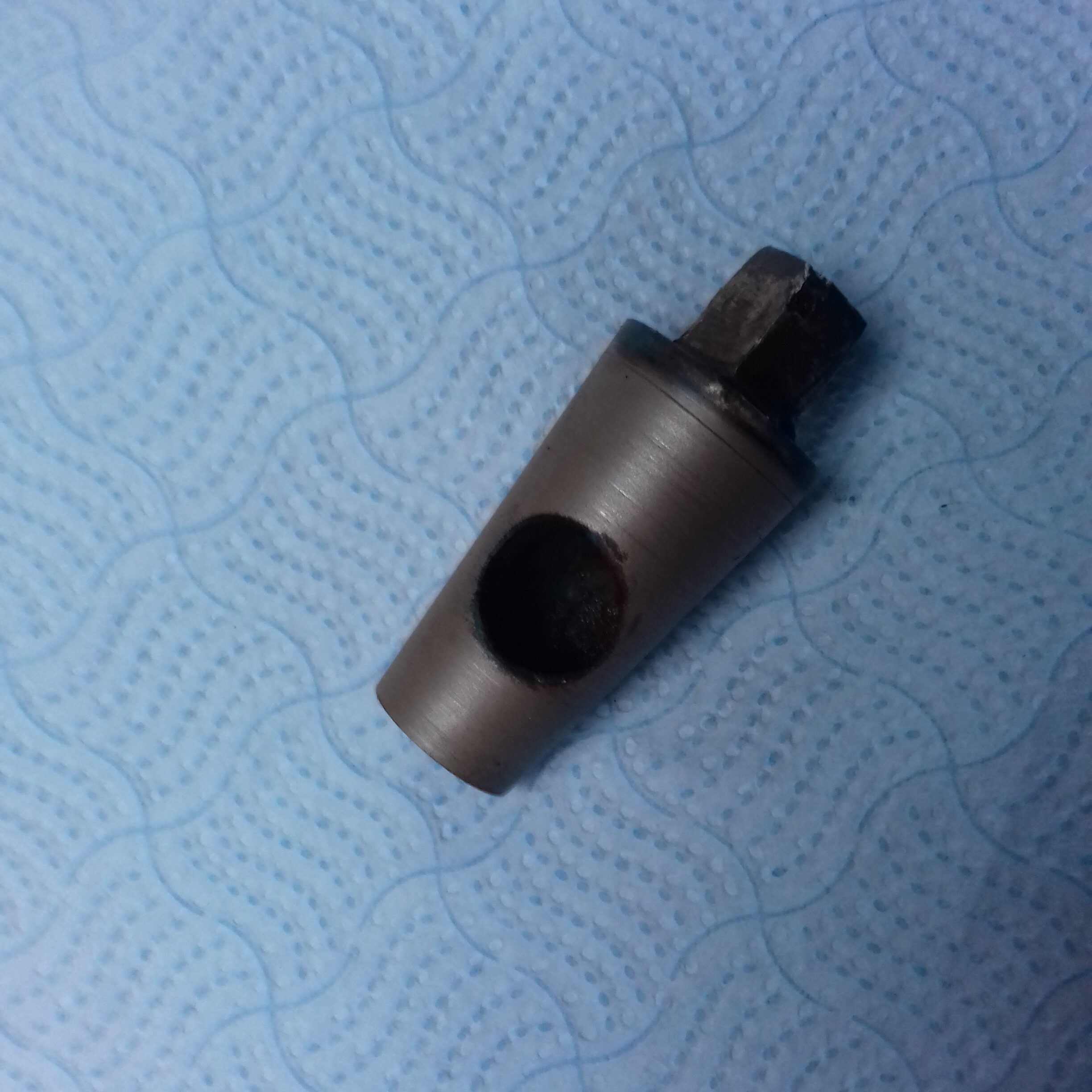
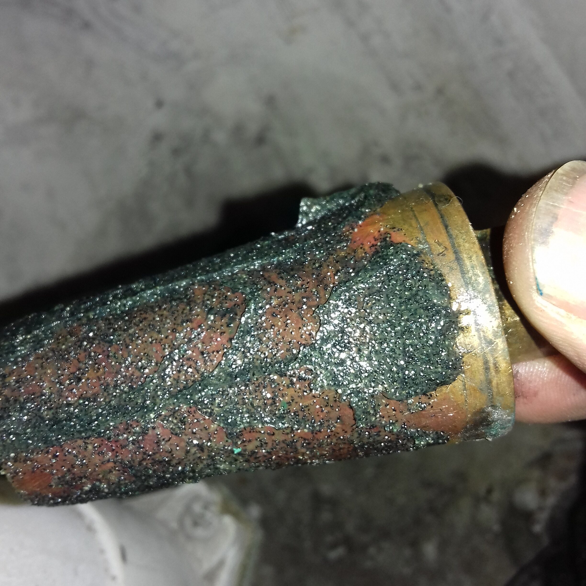 Haven’t done anything like this before but I think they are done enough as there is an obviously extensive cleaned up area on both cones which extends all round the moving part, I take that as meaning there will be a good enough seal once the valve is back together. Still need de-greasing with thinners to get rid of any residual cutting compound then re-grease and assemble them both.
- Started to drill out the 6 corroded mounting bolts for the skin fittings. Three of them have been drilled and hammered out. Will need to tidy up the holes and replace with new 5/16” bronze bolts once I order them. After that is done there will be 4 skin fittings sorted out so I will be almost ready to paint the hull. I get the impression that a lot of these fittings and their attachment hardware seem to have been installed using something like gelcoat as sealing material – Definitely nothing soft or poorly integrated with the hull structure.
Sunday 15th July I managed to get a few minutes to assemble the boat plumbing parts into a siphon prevention valve to go between the water 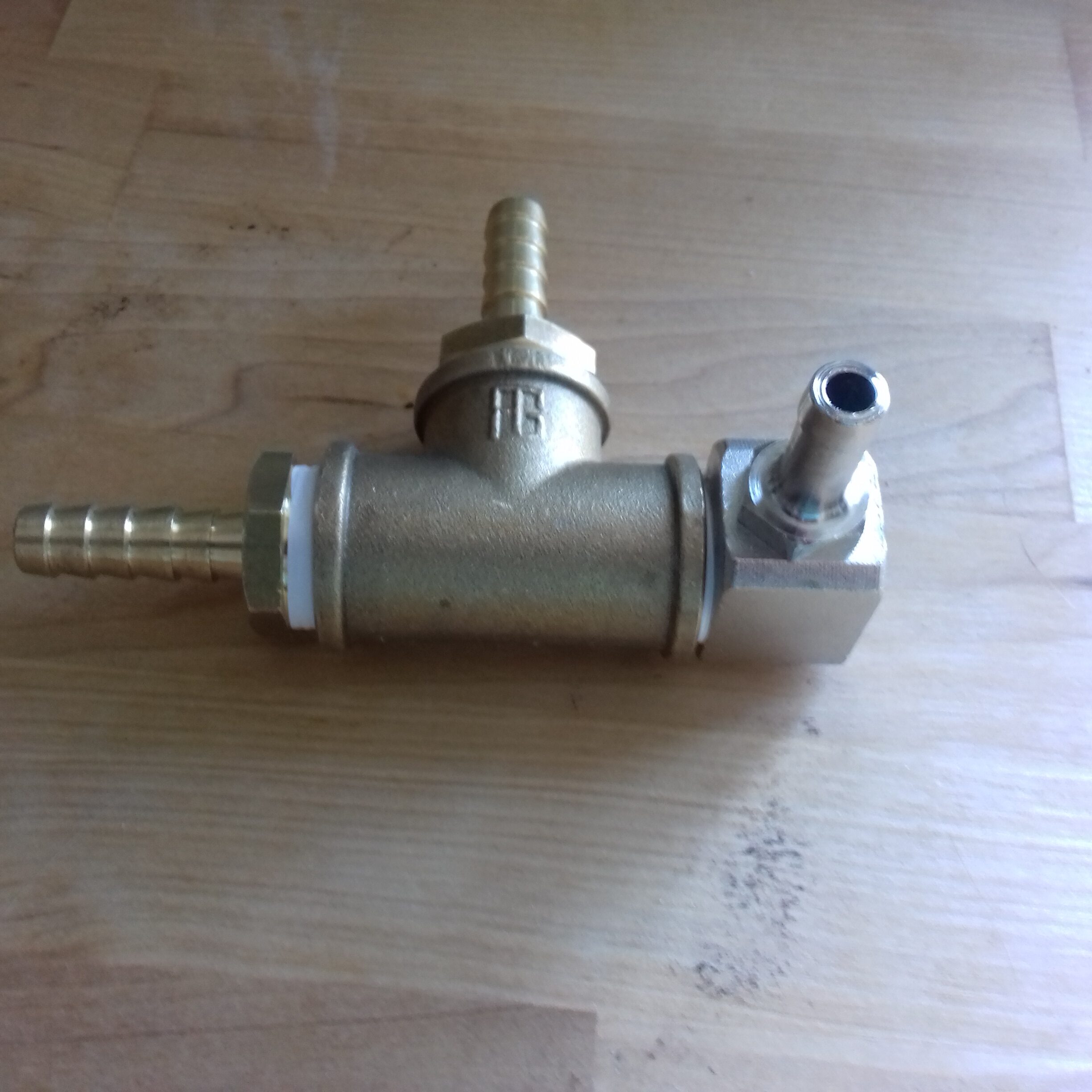 pump and the exhaust resonator cooling inlet. The original installation didn’t seem to have anything similar which is OK providing no hoses leak, the pump impeller stops unwanted water flow and the seacock is always turned off when the engine is not being used. Even with all of those you only need a low lying exhaust output fitting for the system to suck in water when it has run for a while and then cools down. This valve should prevent any of those threats from sinking the boat.
Saturday 21st Finished off the plumbing for the galley sink. 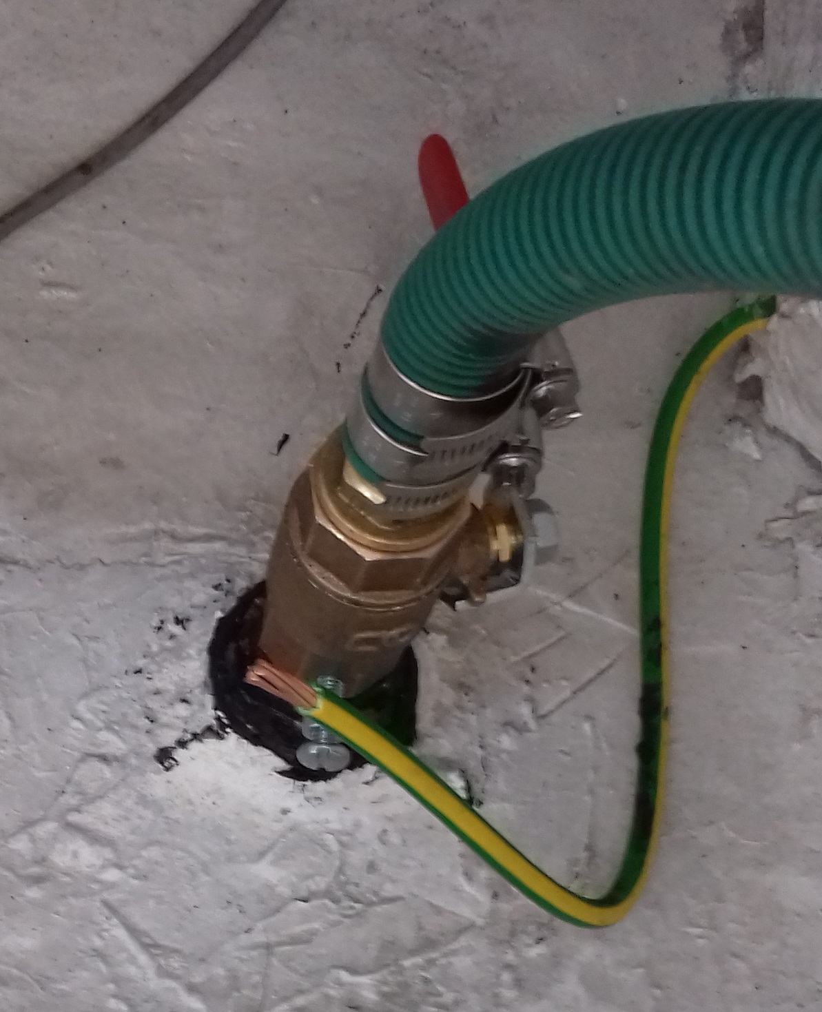 Still needs the grounding wire connecting but otherwise that is finished.
Next job was to get the remaining three seacock bolts out. Shows how bad the corrosion had been as two of the nuts split in half when I tried 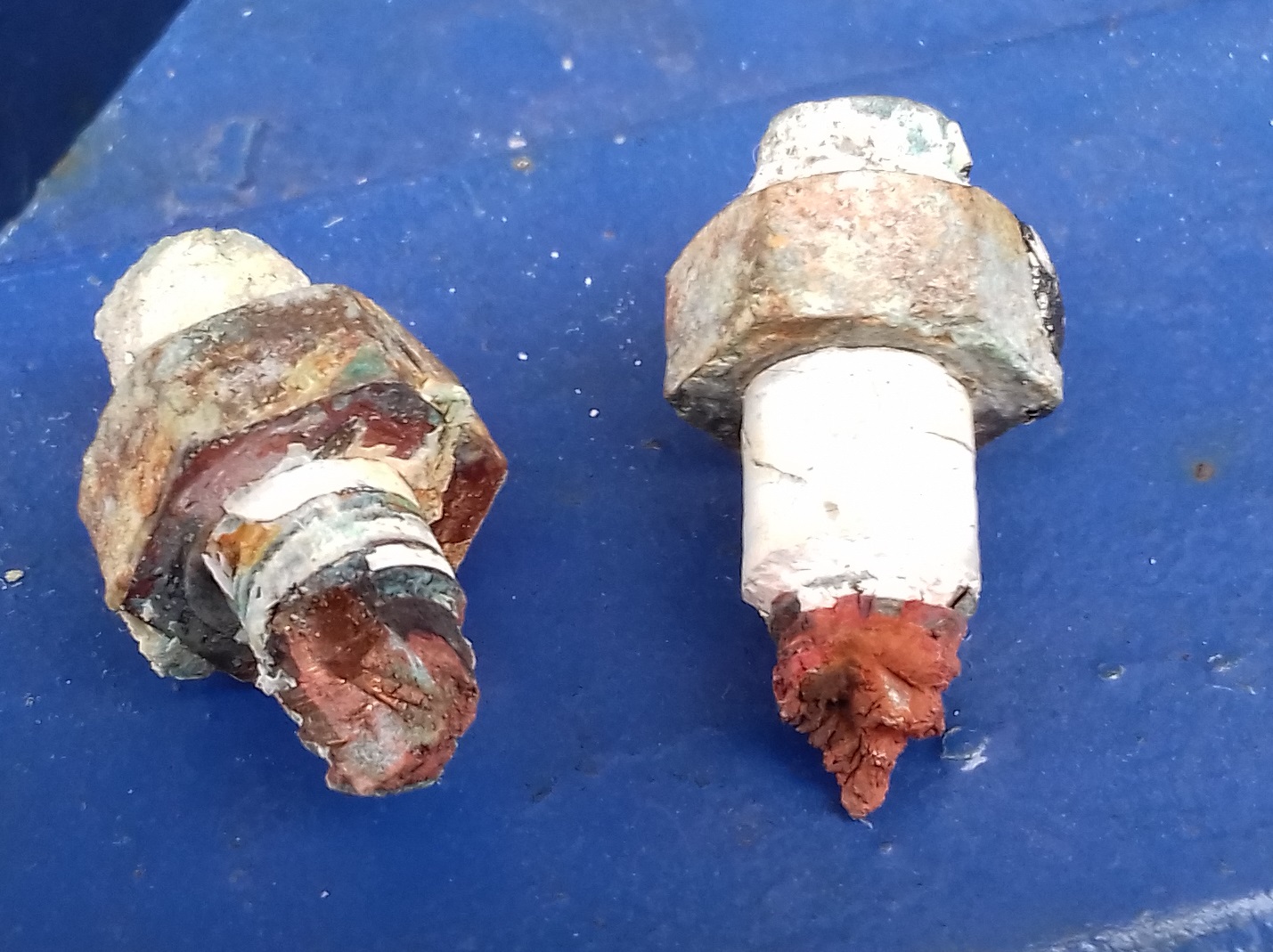 to tighten them to pull the remaining bolt through. Looks like copper rather than brass or bronze where the nut split. There will be more about this in the galvanic protection section.
Sunday 30/9/18 After church & lunch we went to storage. Matthew worked on grouting the bar front and splasbacks in Tin Can Kitchen while I worked on the boat.
- With a little help from Matt I put in all 6 of the new bolts to fix the Blakes type seacocks. Will need to drill out the galvanic grounding tags a little as they don’t fit the non-metric bolts.
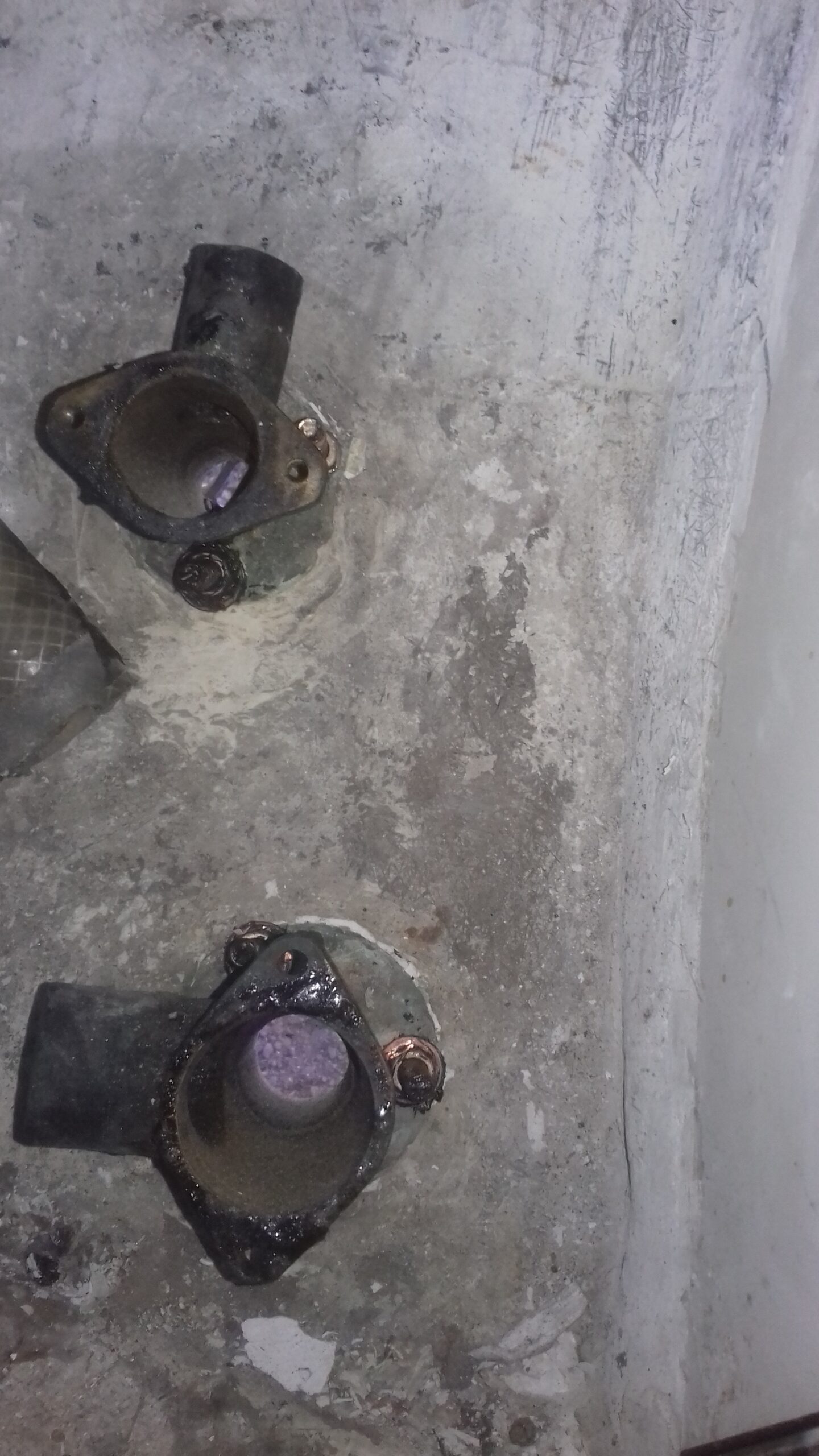 This progress means there is now only the small seacock in the engine bay and the stern tube left as un-secured through hull holes.
I still need to get the hose tails that I need to connect the engine cooling pipes to the seacock but that can wait until the engine is in.
Last but not least important is the exhaust system. This actually didnt need much work at all as the separate water traps and their interconnecting hoses all appear to be ok.
The outlet from the engine’s “resonator” was a larger diameter than the original hose so I obtained a slightly larger piece of the special high temperature rubber exhaust hose and fitted that to the first water trap 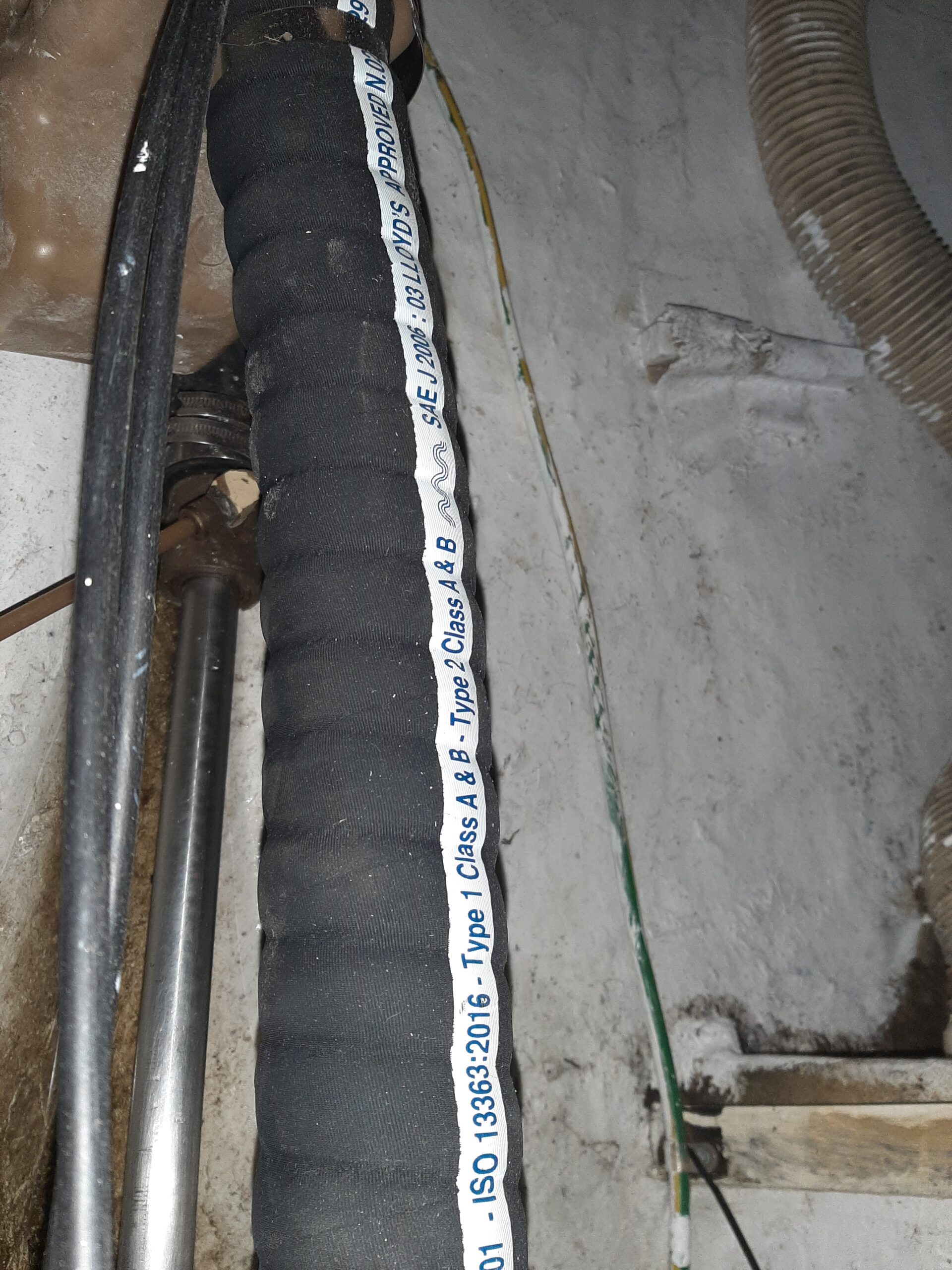 by sliding a short piece of the original hose inside and clamping both of them with larger jubilee clips. The next piece of hose runs to the “Swan neck” which basically is an inverted U bend which takes the level of the tube up to just under the side deck just aft of the starboard locker lid so any waves hitting the stern are unlikely to force water back up from the exhaust outlet but the engine can still eject water and exhaust. There is then a third rubber tube across to the hull outlet which faces downwards on the port side.