I guess one of the major challenges of re-building a boat that you know very little detail about will be making decisions about how to handle restoration of parts that are not present or obvious how they originally were intended to go together. The rudder and tiller are one of those problems as I started off with a solid piece of wood for the rudder, a set of bronze hinges and a tiller but no obvious signs of how the tiller originally fitted to the rudder.
My idea for the rudder is to have it varnished at the top where the wood seems reasonable and cover the lower part with fibreglass tissue in resin then paint it. The lower part of the wood has a few full thickness cracks and will be permanently in the water so I think it needs that level of protection up to the waterline or maybe a little further up. I have a choice of trying to estimate exactly where the waterline will be, following the previous demarcation on the hull or deciding on a non-waterline boundary such as the bottom edge of the lower rudder hinge. It looks as though there is a previous waterline already on the rudder stock probably from metal leaching out of the rudder hinge fitting and flowing into the water. If it is then it lines up fairly accurately with the top of the full width profiled part of the rudder.
So I have sanded off the dirt and scuff marks on the top part of the 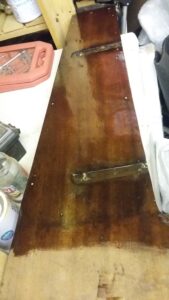 rudder down to a rough line below the waterline. It shouldn’t matter too much if I have varnished wood below the fibreglass cladding for a couple of inches so I think that leaves the options open for a short while. Varnished both sides of the rudder. Tomorrow we will see how the varnish really works out but it looks OK just after it was applied. Next step will be to fill the multiple holes in the top of the rudder where it looks as if there was a large piece of cladding screwed onto the wood.
Just at the moment I am not too sure how best to attach the tiller. Could be bolted through so it is in a fixed position, going by the holes in the two pieces that may be how it was originally done and might be the stronger of the options. However that would mean it permanently took up room in the cockpit. Alternatively the tiller could be a sliding fit into a “socket” made by bending a piece of stainless steel into an inverted U shape. Through bolting that at the top of the rudder will require some packing pieces either side as the tiller is thicker than the rudder but I think it will be a neat and practical alternative. I bought enough M10 stainless steel bolts and dome headed nuts to do either with three bolts through the top of the rudder and, for the latter arrangement, there would be another through the tiller to stop it falling out at the wrong time or even falling overboard.
Saturday 22/10/16 By lunchtime I was making progress with the attachment for the tiller. Used some stainless steel cut from one of the 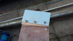 spare pieces that seem to be left from previous efforts with the galley area. It is about 1.5 mm thick so a bit difficult to bend accurately and the end result is about 3 mm wider than the tiller. Not a big deal as I can attach some stainless steel offcuts to the tiller sides to make it a better fit and they will also prevent any wear to the tiller in the future.
Once the whole thing was made and bolted together I gave a first coat of varnish to that and the tiller and a second coat to the rudder stock.
As the last job of the day I cleaned up the rudder mountings using a flap wheel in the drill. They all look much better without the bits of stray paint and the tarnished finish but I am not yet sure how best to keep them looking good.
During the day I had found the steel rod which used to be the pivot, it will need replacing as it is roughly 10mm diameter and the holes in all the mounts are at least 11mm. It also seems to have got bent so it is possible the diameter is not enough for the loads anyway. As I don’t seem to be able to find 11mm stainless steel rod, the new one will have to be 12mm and therefore one of tomorrow’s jobs will be to drill out all four mounting parts to 12mm.
Saturday 28th October. Cut out and fitted the two pieces of stainless steel sheet either side of the tiller; The fit with the rudder stock is now wobble free at least as far as I can test it without actually using it

to sail the boat. Need a couple more coats of varnish on the tiller and rudder stock. Need to do some shopping before I can make much more progress with the rudder. Need White Epoxy paint, woven fibreglass tissue, bronze screws and the replacement hinge rod.
Drilled out all of the rudder fittings ready for 12mm stainless steel rod.
That was about as far as I got with the rudder before we moved house. That involved moving the boat to a storage site instead of our front drive, packing up all of the boat parts as well as the house and garage contents. The actual moving itself and setting up a workshop in the new garage (which is a lot smaller). There was also the small issue of university open days for our youngest daughter.
The next post will be about restoring the engine and electrical systems which I worked on almost to the exclusion of other boat items so it was almost 4 months before I did any more work on the rudder.
Friday 17th Feb 2017 – Plan for tomorrow is to get started on the fibreglass sheathing of the rudder. Starts with ensuring the resin is warm enough to set so the can is spending the night inside to help achieve the first part tomorrow  .
.
Saturday – Woke at 6:20 so got up and was in the garage a little after 7:00. First side of the rudder reinforced with random chopped strand fibreglass up to where I estimate the water level will reach. Cured reasonably with a little help from the fan heater. Will clean up the edges later today and then do the second side tomorrow .
The following weekend I added a layer of glass tissue to each side of the rudder. This is much finer glass fibres and is intended to cover up any surface irregularities created by thicker layers underneath. There aren’t any photos of this stage as none of this job is particularly photogenic – If it is wetted out correctly with resin the glass becomes transparent and all you can see on photos is the brown colour of the underlying wood.
Having completed the reinforcing, the rudder part of the project took another rest period while I did other jobs but eventually I started to re-fit the hinges to the rudder and hull. The rudder part was very simple as the hinges were already drilled out and the rudder itself had grooves in the right places. The only complexity with doing this job from scratch would be making sure that the screws from the two sides don’t coincide.
The hull mountings proved a little more challenging because the collection of random fastenings that came with the boat did not include anything identifiable as the bolts for this job. The lower hinge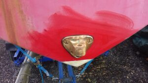 was easy as the mounting bolts for that end up in the single layer hull section under the cockpit floor. Installing the bolts for that was the last job I did before the engine went back in and I included a connection to the galvanic grounding system by putting the terminal between one structural fixing nut and it’s locknut partner. Possibly not essential as the dissimilar metals (Bronze Hinge & Stainless steel rod) are just above the waterline and shouldnt be permanently in contact with sea water.
The hull had a set of three holes on in the right place on the outside to be the top hinge mounting but the holes did not go right through the 4″ thick transom (which was hollow anyway). There appears to be some form of captive nut system inside the moulding but I totally failed to identify any obvious thread which fits. The only way I could attack that problem was to drill out the original internal fittings and use new bronze bolts with washers and a pair of nuts inside the gap between the two fiberglass layers. Actually doing the “drilling out” proved a little harder than the theory as it turns out there was a stainless steel nut inside each hole and I initially chose just the wrong size of drill bit which got stuck in one of the nuts and broke off indide the transom. A lot of non-so careful drilling later and I had a larger hole than intended but without the interfering metal – Soon fixed with filler.
Having achieved holes right through the hull and cockpit lining moulding I filled the gap between them with expanding foam before re-drilling the holes and then using a hole-saw to remove a suitable diameter piece of the cockpit moulding to allow me to add the washers  and nuts. After lining the holes with fibreglass, the nuts were positioned and tightened using a deep version of a socket set. All rather messy as the bolts were coated with marine sealant before I put them in as an attempt to keep the water out of the holes. No need for complicated packing pieces inserted into the hull though as this is old enough to be a single thick layer of GRP rather than modern sandwich construction.
Finally on 21st April 1019 I could finish the pivot rod by drilling out 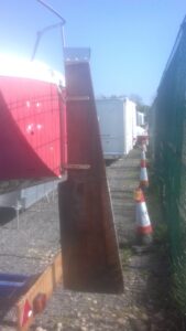 two holes to take R clips top and bottom and do a trial install of the rudder. Just leaves me to paint the under water section.