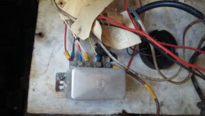
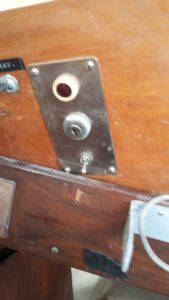
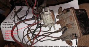
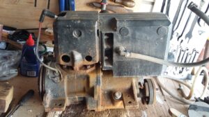
On initial inspection the engine appeared to be installed although not bolted down. There was an electrical panel in the boat with the engine ends of the cable labelled as to where everything needed to go but nothing actually connected and just for luck another electrical system as spares. Throttle and gear controls were in place in the cockpit recess but not connected to the engine. No fuel connection, no cooling water connection, exhaust system present but not connected to the engine. The propeller and it’s shaft were among the collection of metalwork inside the boat as were various bits that looked like universal joint parts and a cutless bearing.
How hard can this be for someone who has fixed their own cars for 40 years and is fresh from working to restore a VW camper van? How long can this take ?
In September 2016 I didnt yet realise just how much of a kit of parts this really was. The initial plan eventually got achieved but the timescale was a lot longer than anticipated.
Somehow the conventional method of mounting a shaft bearing had failed as bits of the fiberglass ‘deadwood’ had cracked off leaving holes where there should have been studs. The bits of random metal included a neatly welded up casing which looked as if it was designed to cover the aft section and replace the missing studs so that was the solution I eventually used. Here is what I wrote in my diary at the time –
10/9/2016 “Investigated the state of the propeller, rear bearing and it’s stainless steel mounting piece. There are a couple of potential problems but nothing I am not confident I can sort out. Might not end up as the neatest solution to mounting a stern bearing but we will see what can be achieved. At the moment my main concerns are to work out the best way of attaching the stainless steel component while being able to ground it to the galvanic protection (and probably the lightening conduction wires as well. This and the propeller seems like a useful piece of metal to use as the exit to ground potential). All the propeller thrust is taken by the engine mounts so the attachment doesn’t need to be particularly strong. Maybe can clean off paint down to the fiberglass and epoxy the metal onto that. ”
The identity of the current engine was fairly obvious from the manual and consulting the internet regarding Vire marine engines (Particularly the website for the only identifiable source of spare parts and replacement engines in the UK – https://vireengines.com ). Makes sense for it to be the bigger version as it has the electric choke unit which is described in the handbook as being fitted to the 12 Hp version. Similarly this was not the engine that matched the electrical system as there was no wiring for the choke.
I have evidence of spare parts being fitted in 1996 as there are receipts in the handbook but nothing recorded since then.
14/9/2016 “I think the next priority needs to be to take the engine out of the boat so it can be checked over on the garage bench. I don’t know how long it is since it has run so there could be a damaged fuel pump diaphragm and the water pump impeller also needs checking. I also don’t trust the old petrol pipes to be secure so will check or replace those and also the cooling water pipes.
After reading the engine installation section of the manual and the inland waterways boat safety manual, I also decided that the fuel and cooling systems needed to start from scratch for safety reasons. By the start of November 2016 I had the start of a plan and was ordering parts for the fuel system.
Lets start with a brief description of a Vire 12 for those like myself at the start who know nothing about these. It is a 12 HP single cylinder 2 stroke petrol engine with magneto ignition. Built in Finland in the 1960s by a company that subsequently morphed into one of the current manufacturers of inboard engines and generators. The cylinder is directly water cooled (ie sea water in the cooling passages!) with the used water being mixed with exhaust gasses in a large silencer type casing before the mixture goes overboard via a series of water traps designed to prevent reverse flow of seawater into the engine when it is not running.
As well as pull rope starting, the engine is fitted with a Dynastart which is a combination of starter motor and dynamo in a single unit. I had never come across this system before but it apparently is common on veteran and older vintage cars as well as older boat engines. The drive connection between the flywheel and the Dynastart is via a belt so it looks just like a normal dynamo. The fuel pump is a simple diaphragm system driven by pressure changes in the crank case and feeds into a conventional multi jet float chamber carburettor.
The drive system has forward and reverse gears selected by a big lever on the starboard side which selects one of the two centrifugal clutches inside the gearbox.
” Current setup on the boat uses nylon reinforced plastic tube and a plastic inline petrol filter, neither of which are safe in the event of any overheating or even a small fire. There is no fuel shutoff valve and no sedimentation bowl, both of which I have been persuaded are important for reliability and safety.
General plan is to have a shutoff valve in the fuel locker (a solenoid one wired to the ignition switch and a manual bypass valve so the engine can be run in an emergency if there is an electrical problem) feeding fuel via metal piping to a sedimentation bowl close to the engine. That will feed direct to a length of braided steel covered flexible fuel hose to the fuel pump and then on to the carburettor. The last two pieces of hose will replace the existing Vire parts and use the original end fittings. Our camper van fuel system is similar (without the sedimentation bowl) as many vans seem to be destroyed by fires as a result of the fuel tank being above the engine. As with the boat, any fuel leak is under slight pressure and any damage to the rubber hose due to heat or fire potentially allows the tank to empty into it making it impossible to have a realistic chance of putting even a small fire out.”
The project logically splits into discrete sections which I can write about without too much overlap but the reality was that many of these were being worked on in parallel and there were dependencies where some things had to be finished before steps of others could be attempted. Most obviously the work between the engine and the transom had to be done before the engine could go back in because I can only just crawl over the top and into the space under the cockpit floor.
The first active work on the system was to replace the electrical panel that was already in the boat with the alternative wiring loom and new control boards. This was mainly to accommodate the choke and fuel solenoid. There are three separate sections for the wider “electrical” project dealing with galvanic corrosion protection, the engine electrical system and the evolution of the “house” system including solar panels.
The second project section was the restoration of the engine itself and modification to match up with my new control levers. Anything about electrical systems in this particular blog section refers to bench testing rather than in the boat.
Fuel and cooling water plumbing were the third project section.
And finally there is a section about re-installing the rest of the drive train and aligning the engine.
To avoid confusion I am writing this in 2020 but it logically fits in 2016 when the diary entries were written so here are some before and after photos to show how it s turning out –