Somehow the simplest of things seem to take a long time when working on a boat. I was only just starting to realise that with the discovery that almost all of the hull skin fittings were fitted with inadequate gate valves which seem to be conventional domestic plumbing versions so are likely to corrode and are liable to jam in the wrong position when most needed. All of them will need to be replaced with proper bronze skin fittings and ball valves. Also will need to re-connect the galvanic corrosion protection to everything but more of that in a future post.
A brief investigation of the standing rigging, particularly the roller furling system, uncovered some more problems to research and plan to solve.
To start with I couldn’t work out how the halyard was supposed to be  tied off as it was mounted on the rotating part of the forestay (which seemed right) but didn’t have a cleat which rotated in the same way. Then I realised that the rotating bearing part was supposed to be hoisted up the aluminium track and actually the original halyard in the mast was supposed to do the job while the bearing allowed the sail to be rotated without tangling up the halyard. Having subsequently looked at the internet it seems there were always problems with this roller reefing system if the halyard runs too parallel to the forestay as any degree of drag in the bearing means the halyard wraps around the aluminium and can stop you reefing. There is quite a bit about this problem either on forums discussing the same system I have or more general tips such as these pages (http://www.sailboat-cruising.com/roller-reefing.html http://www.cncphotoalbum.com/doityourself/rollerreefer/rollerreefer.htm and http://www.inyourfootsteps.com/sailing/tips/9/246/a_stubborn_and_resistant_headsail_furler_that_jams_or_releases_and_jams_alternatively_when_furling/ ).
Having removed the extra home-made halyard mounting strap I started to see if I could get the bearing apart to add some more balls to the system. That meant I needed to get the forestay off the mast which was why I started the battle with the mast head pins.
Managed to get the one out which held on the forestay and also removed the remains of the backstay. Took a bit of ingenuity though – I used a large socket placed over the pin to be removed and then clamped it across the head casting as firmly as I could using a 9” G clamp. That didn’t shift either of the pins on it’s own but both pins yielded to the sustained pressure combined with a sharp blow to the G clamp using the lump hammer. Once they were moving I could drive them the rest of the way out using a light hammer and a mild steel bolt as the driving tool. Will need to measure the pins to see if I can drill out the casting very slightly larger or need to file or grind down the pins before re-assembly.
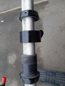
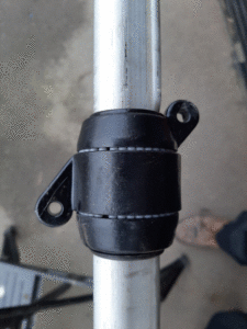
Having got the forestay and furling mechanism separate the next task looked simple to start with – The bearing is in 3 parts, A main piece which is the bit which slides up and down the aluminium sail track, the hoisting mechanism is the middle piece with a series of plastic balls between it and the other two pieces and finally there is a top piece attached to the core via a screw thread which controls the rolling tolerance for the plastic balls. The positioning of the screw section is locked by a hex socket grub screw. As is often the case, I have several Allan keys which are just a little too loose to fit (probably metric and the original is an imperial size) and only a few which are right. First one which fitted correctly might as well have been made of cheese, Didn’t shift the grub screw at all just bent the Alan key so I tried to help it along by applying torque using an adjustable spanner. That made the shorter limb twist and snap. The other key which fitted started off similarly so I ended up drilling out the grub screw. At least I will be able to re-tap the hole and use a bigger size of grub screw during the re-assembly. Seem to have around 60 plastic balls each around 4mm diameter. Given that this is a UK product from the 1970 s they are likely a non-metric diameter so am aiming to replace them with the 5/32 “ delrin balls from this supplier – http://simplybearings.co.uk/shop/Loose+Balls+&+Rollers-Plastic+Balls-Delrin+Plastic+Ball+Bearings/c23_5027_5028/index.html. Will order 1 pack of 100 to be certain there are enough to replace all of them and remove the majority of the gap (total cost £17:99).
I am not all that keen on solving the wraparound problem by having a halyard which is not parallel to the forestay either because of the location of the sheaf or via attaching a loop to the mast to divert the last part of the halyard when fully hoisted. Neither seem likely to give adequate control over tensioning of the luff of the sail and will also put sideways pressure on the forestay. I intend to try fitting an additional thin line which can be tightened after the sail is hoisted and acts to link the middle piece of the bearing back to the mast, that wont need much tension but will stop any tendency to wrap the halyard around the metal track.
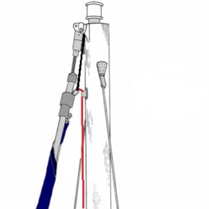 This picture (modified from the last of the web forum pages above) shows my idea with the red line being my new piece of cord and the black the original halyard.
For future reference the “Bulldog” name on my reefing system appears to be a successor to the “Rotostay” system and may even be identical as apparently the company took over manufacture. This website (https://corribee.org/technical/roller-reefing ) gave details of suppliers who had spare parts in 2012. This one has PDF files for the original installation and details of a replacement bearing kit using 3/16” or ¼” balls (https://verl900.wordpress.com/technical -articles/rotostay-furler-bearings/ ). Measuring the remaining beads suggests the diameter is more like 5/32 or 11/64 although that could be due to wear on 3/16 “ balls. The instructions for a maintenance kit say to fill the two tracks and then remove one bead from each. They do give numbers but are using larger diameter beads so the different models may use different bearings. Hopefully the mechanism will work better with a more adequate number of new balls and a suitably re-arranged sail hoisting.
So that’s the plan but it is going to take a few years before we get to implement the system and test it out so here is the sneak preview of the tidied up sliding mechanism.