Lots of people have written about whether or not you need galvanic protection for metalwork in contact with water. There are plenty of boat books which try to describe the corrosion problem and university level chemistry education does not give me any particularly different slant on that. What I do have though is some electrical knowledge combined with observation and a growing understanding of the implications of waterproof compartments in a boat hull. Hopefully I can explain the reasoning behind my version of this protection system and particularly my thinking about extending the protection of external metals from corrosion to also protecting metals that are in wet areas inside the boat. That is not something I have ever seen elsewhere but which I have realised from the behaviour of some of the older metal parts of Rathenice and recognised from corrosion that happened when rain water got into the hull.
Let us start with a little about the chemistry of metals and how it is linked to the movement of free electrons both in the solid and ions in any solutions in contact with the metal.
I am confident that anyone still reading this is familiar with the fact that most metals are shiny when they are freshly made or recently cleaned. A very few special metals like gold tend to be inert (not react), others that form a very thin transparent layer to protect the surface (eg aluminium, Chrome, Stainless steel etc) but almost all metals will become dull when left exposed to the air or water because of reacting to form a visible layer which is often opaque and coloured. The non-chemical terms for this range from patina (when we admire the visual effect such as a green copper roof or an old bronze fitting on a boat) to more derogatory terms such as tarnished, corroded and rusted which carry the suggestion that the object is unsightly and damaged.
As a pure element or an alloy, the metal atoms form a regular lattice structure which allows each atom to share it’s relatively free electrons with it’s neighbours. Normally this exchange will be entirely random but, with the right external influence, the movement starts to have a slight excess in a particular direction and the metal is conducting electricity.
The surface of the metal can react with other chemicals that it comes into contact with and, as oxygen is a very reactive component of our atmosphere, that is often an oxidation reaction. There are two definitions of oxidation to a chemist so as well as the obvious “adding oxygen” to an atom to form an oxide you can also “remove one or more electrons” to form an ion. This is helped by the presence of water and other dissolved substances which can be reduced (gaining an electron) as the balancing part of the reaction. Any metal ion formed will be more or less associated with with one or more oppositely charged ion(s) to form a salt either in solution or combined with captured water molecules as a crystalline substance.
Formation of an ion means that the affected metal atom is no longer part of the metal lattice and can migrate away in the solution. Depending on the metal atom that has become ionised there will be a different amount of difficulty and energy associated with the change and this property of the reaction can be measured as a voltage.
So hopefully you can now see that we can associate the difficulty of reacting with a particular metal atom with a potential / voltage and the number of such events with the number of electrons flowing ie an electrical current.
The voltage for each metal that is present predicts which will react in preference to others so more anodic ones react (and disappear) first and more cathodic ones are relatively protected. Any oxidising reaction that is progressing will consume almost all of the available material at a lower voltage before starting to react to a significant extent with the next available material. This is the principal behind coating steel with a sacrificial layer of zinc in galvanised iron roofing (or bridges, metal buildings, cars etc) so the zinc is consumed before the iron starts to react. –
Table of metals (Adapted from Steward 1970 , Boatbuilding Manual., P33)
| Metal | Property |
| Zinc | Anodic Sacrificed |
| Pure aluminium | |
| Aluminium alloys | |
| Steel | |
| Cast Iron | |
| Lead | |
| Tobin Bronze (Naval Brass) | |
| Copper | |
| Silicon Bronze | |
| Monel | Cathodic Protected |
If you want to regard that as an incomprehensible theory then that is fine, but hopefully you will see that it allows us to explain and predict some of what happens with mixtures of metals in contact with water (particularly sea water with all those chloride and other counter ions) and helps us know how to protect the random shaped lumps of metal which we prize as important parts of a boat.
Real world metal corrosion
So lets look at what happens with a piece of brass or bronze immersed in sea water both in theory and in practice with old parts of my boat. You will appreciate that I dont completely know the history of the boat but there were no obvious wires anywhere near to the two seacocks associated with the heads so it was unlikely they were ever connected to the anode. This is quite a common occurrence as people think that there is no electrical connection with other metal items so a particular part of the boat does not need galvanic protection however corrosion can happen within an alloy and between dissimilar metals in the same item – eg a steel ball inside a bronze seacock or a brass screw attaching a steel part.
When I tried to remove the bolts that attached the seacocks to the hull they were very weak, heads broke off and nuts snapped in half rather than un-screwing.

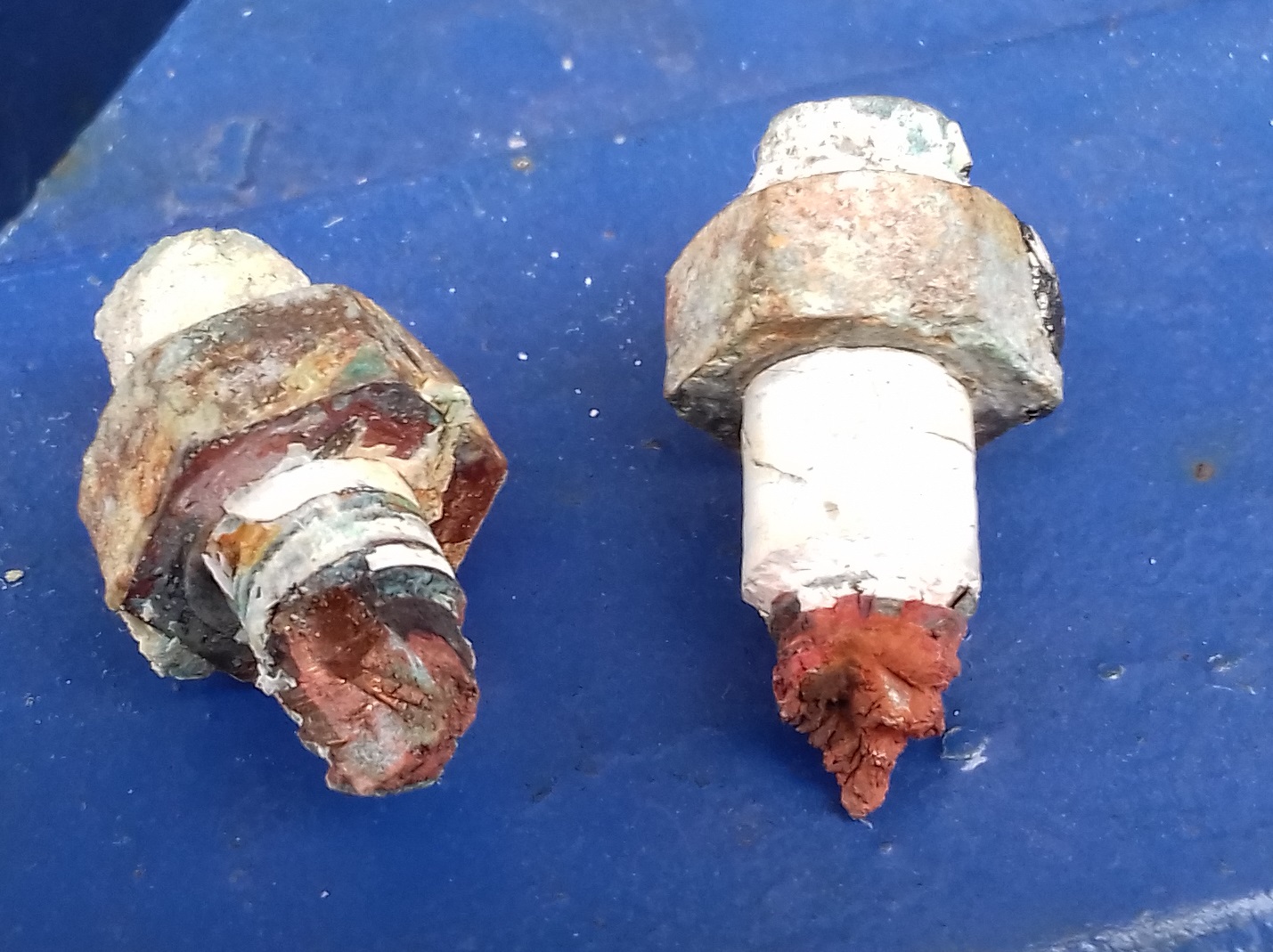
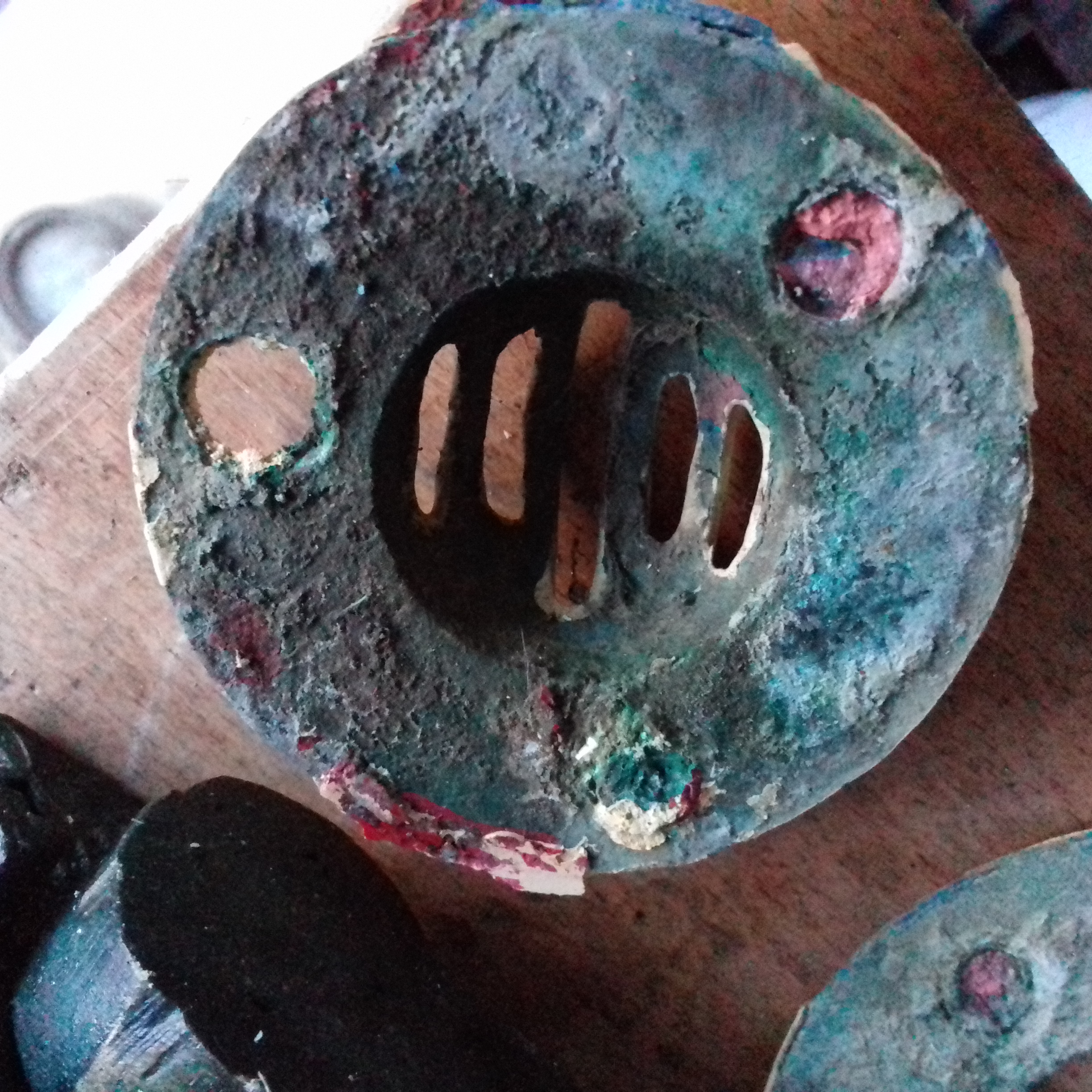
I also referred to them as “Carroty”, an old term sometimes used when a brass or bronze fitting becomes weaker and much more orange coloured than originally. You can see the “copper” colour on the broken surfaces of the fittings and the underneath of the countersunk bolt head that remains on the strainer. There was also rather a lot of green colouration probably due to copper salts present on unpainted metal surfaces. Brass is basically a mixture (alloy) of Copper and Zinc and that becomes known as bronze when other metals are included as well (often the type of bronze is named after an additive eg Silicon bronze used for marine bolts, screws and castings). The electrochemical theory goes like this –
- Within the brass / bronze fittings the copper and zinc are in separate small areas which are in electrical contact with each other and also with the sea water. On a microscopic scale the different metals set up a competition leading to selective loss of the more anodic zinc atoms from the surface of the alloy. The electrical current flowed between the two different metals with the copper as cathode (protected) and Zinc as anode (sacrificed) and a return path as ions flowing through the water. As time went on (40 or so years for these bolts and nuts) the effect penetrated deep into the fittings leaving behind a porous copper object which is much weaker than the original alloy. Indeed it seems the copper may also be starting to corrode as well.
- What if the whole fitting had been electrically connected to a sacrificial anode ? – On a fresh water boat the anode would be magnesium which is even more anodic than the zinc. The presence of this immersed in the same conductive fluid and electrically connected to the fitting would prevent the potential rising above that required to oxidise the anode so both metals in the alloy would have been protected. This works providing the electrical connection on the boat and conduction through the water was sufficient to provide a complete current loop. In practice this means an anode will only protect within a particular range so large ships may need multiple anodes. Magnesium doesnt last long in salt water so a much bigger piece of zinc would be used and that would slowly dissolve instead of the zinc in the fitting because of the smaller surface area of the latter. Once the anodes had completely dissolved, or if the electrical connection became poor, then the zinc in the fitting would gradually become the sacrificial metal. – Hence you need thick well connected wires, to check the cables regularly and replace the anode before it gets too small.
Maybe those bolts and nuts would have still been serviceable if the fitting had been connected to sacrificial anodes?
Most of the effect of the extra metals in bronze is to add strength and stabilise the surface by forming a protective coating which that slows down the electrochemical effect that we saw with the bolts. In the case of the tapered seacock plugs and seats, you may now recognise a thin layer of carroty bronze on the pictures where I had just got them apart and only yellowish bronze once I had ground them ? In this case the bronze fittings were protected compared to the bolts which may have been acting as an unintended anode. You will notice that there are two types of bronze at different positions in the table, stainless steel was left out of the table because there are a lot of slightly different mixtures (not even as simple as the A4 or A2 distinction you may come across when shopping for bolts) and different types would appear almost at random in a full version of the table.
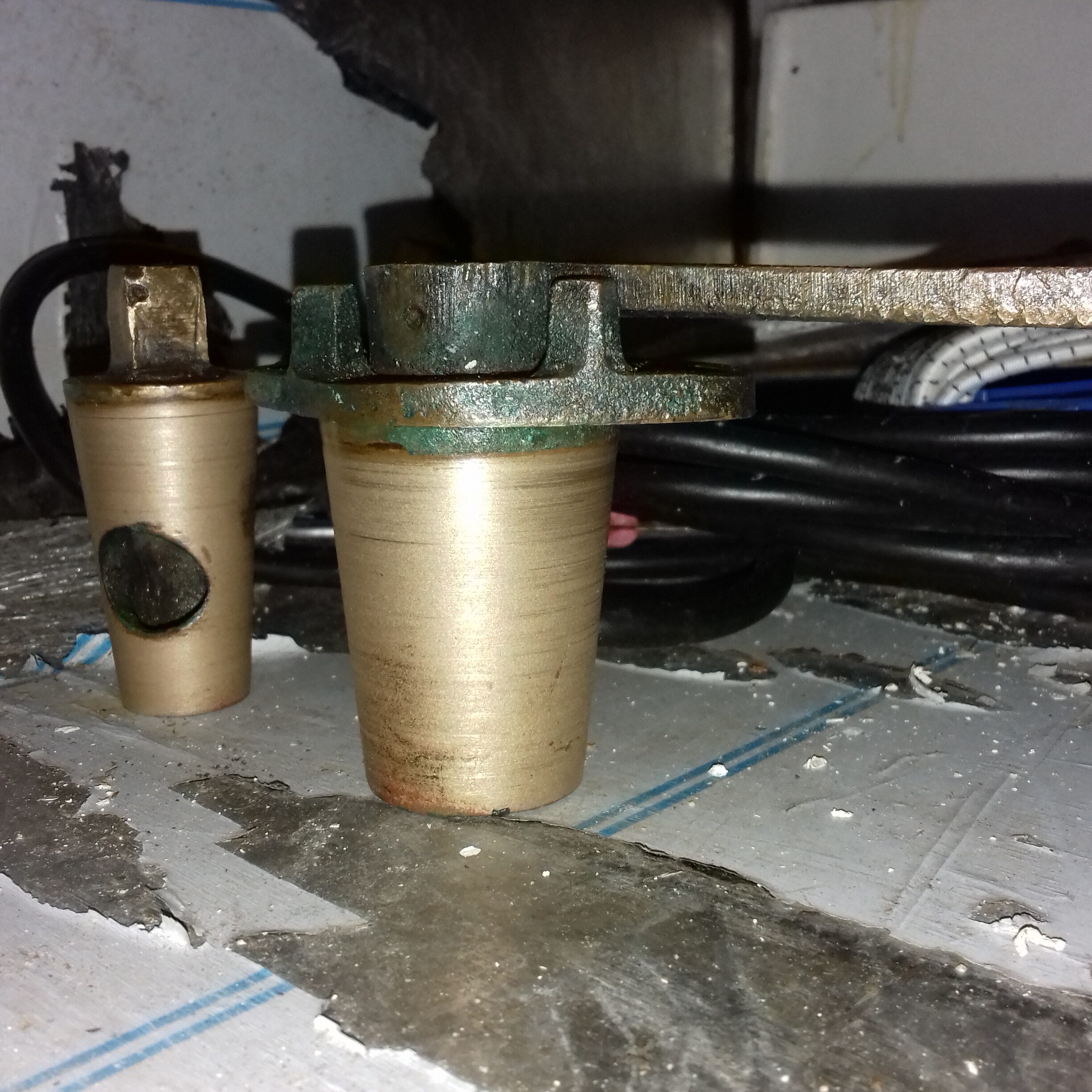
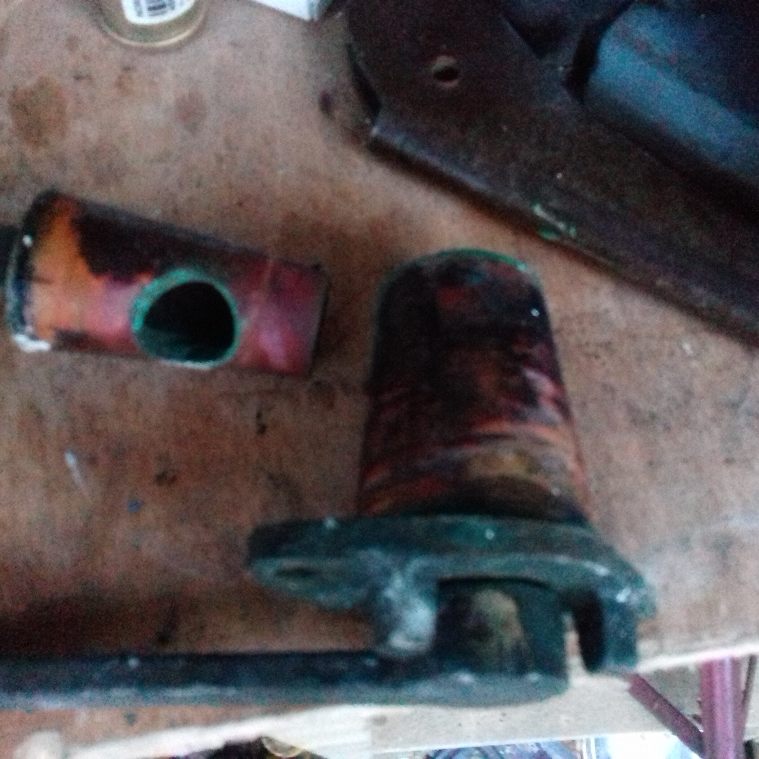
So the example above shows the effect of immersion in seawater outside the boat! That is all conventional galvanic corrosion and protection theory but did you notice something else?
Those nuts on the inside of the hull were also corroded and carroty but they had not been immersed in seawater (or at least not for anywhere near as long as the external fittings. The normal external anode theory & solution tells us nothing about that so how do I explain it? You may recall that I mentioned needing a return current loop provided by conductive ions in the sea water. – Well the external anode would not be able to protect against galvanic corrosion set up within or between components in bilge water or a condensation film inside the insulated hull because there is no return conduction path to the anode. I suggest we also need a sacrificial anode in each isolated “pool” of bilge water.
Is that the same as keel bolts rusting inside the hull despite there being a sacrificial anode on the outside of the hull ? Again the bilge water in contact with those bolts is a different collection of water which is physically and electrically isolated from the main anode. There is no return path to the internal water and therefore the anode can provide no protection against corrosion within the hull. Do you still need more evidence for having multiple internal anodes? – Well it is at the end of the next section about setting up my system, see if you can spot it in one of my photos before I reveal the problem.
Connecting all of the immersed metalwork and the main anode.
Before I start describing the installation in Rathenice, there is one web page I have seen which argues against connecting all metal components that are in contact with the water. It came from America as an advertising email for ‘Practical sailor’ and seems to me to describe a particular problem caused by their AC electrical systems so may not be relevant in other countries. To be honest I am not sure about a ‘technical’ article that gets the wire colours wrong in their diagrams, you will see white and green swapped over in this figure from an earlier version of https://www.practical-sailor.com/mailport-ps-advisor/ps-advisor-grounding-and-bonding (I have crossed out the incorrect colour labelling in the diagram below).
Even if we disregard their error, the neutral (White) and safety ground (Green) connections in the power grid are connected together close to the point of use when both are grounded at the local transformer. Having it connected to a current carrying wire (and especially using it as a second neutral wire like their diagram!) can contribute to the ground connection being at a higher voltage than would ever be the case in Europe where the connections would always remain totally separate. In the event of an on-shore or boat wiring error you could even have the “ground” wire permanently at 110V. If the safety ground coming onto a boat is at a significant voltage then there can be stray currents through the water in marinas and the argument is that rather than flowing through water, this current can take a short cut to the source through a boat galvanic grounding system which will cause corrosion at a very rapid pace. The problem of stray current is thought to be enough for them to warn against swimming in US marinas to avoid the possibility of a fatal shock (https://www.practical-sailor.com/marine-electronics/preventing-electric-shock-at-the-dock ).
I may criticise their diagram but I was impressed enough by the article to use their wire gauge recommendations as the basis for both the lightning and galvanic grounding cables. They do redeem themselves in the final paragraph where the actually agree with my ideas even if reluctant to apply it in the USA. – ” Today, the technique of bonding everything together would still work fine if your boat spent all its time on the high seas, in remote anchorages, or in marinas that were wired perfectly and in which all of the nearby yachts were wired perfectly. Having underwater metal bonded together in crowded marinas today, however, is asking for trouble. ”
Lets start with a list of the metal objects which are either permanently or regularly immersed in sea water –
Lower rudder hinge, mounting bolts & pivot pin
Exhaust outlet through hull fitting
Propeller & nuts
Prop shaft & key
Cutless bearing housing & fixing plate
2 cooling water inlet through hulls & seacocks
Galley drain through hull & seacock
2 seacocks associated with the heads
Anchor & chain – Well they are galvanised so protect themselves.
First obvious problem is that the prop shaft and propeller need to rotate so are not easily wired to anything. Some boats have a brush system to ensure this can be connected into the protective wiring system (also to achieve an effective radio ground) but I have seen people question the effectiveness of this arrangement. For my purposes this will be protected using a clamp on zinc anode attached to the stainless steel shaft.
Most of the items on the list are potentially accessible from inside the boat so can be wired together using conventional high cross section grounding wire ( 16 square mm conductor / 75A capacity). Because we need to achieve good electrical contact all of the terminals were soldered as well as crimped onto the ends of the wires. The bolted items were easy because you just attach the item to the hull normally then add an extra nut to hold down the electrical terminal, I used flat washers and serrated type lock washers with this method so I can be reasonably sure that there is a good connection to the metal despite any potential for patina to form on the surface.
You would think that it is a common requirement to attach a grounding wire onto through hull fittings and sea cocks and historically they would have been made with a suitable threaded connection but that now seems to be rare in commercial ones. At best you might get a large tag to tighten down under the mounting nut but usually nothing seems to be provided.
A particular problem is getting a good seal and an electrical connection between through hull fittings and the associated sea cock. Water leakage is prevented via sealant and / or PTFE tape in the screw joint but of course that is an electrical insulator. Leaving either part of that assembly un-connected will invite corrosion so here’s what I decided to do –

Assembly process is to install the through hull first and drill & tap the hole in the threaded portion of the seacock. Now install the seacock onto the through hull with sealant. PTFE etc. Place the nut about half way up the bolt along with the lock washers, terminal and flat washer and screw the end of the bolt into the tapped hole. There is not much thread so tighten carefully but firmly – The end of the bolt should cut through the PTFE tape and make contact with the through hull threads. Finally tighten the locking nut against the outside of the seacock to achieve a good electrical connection.
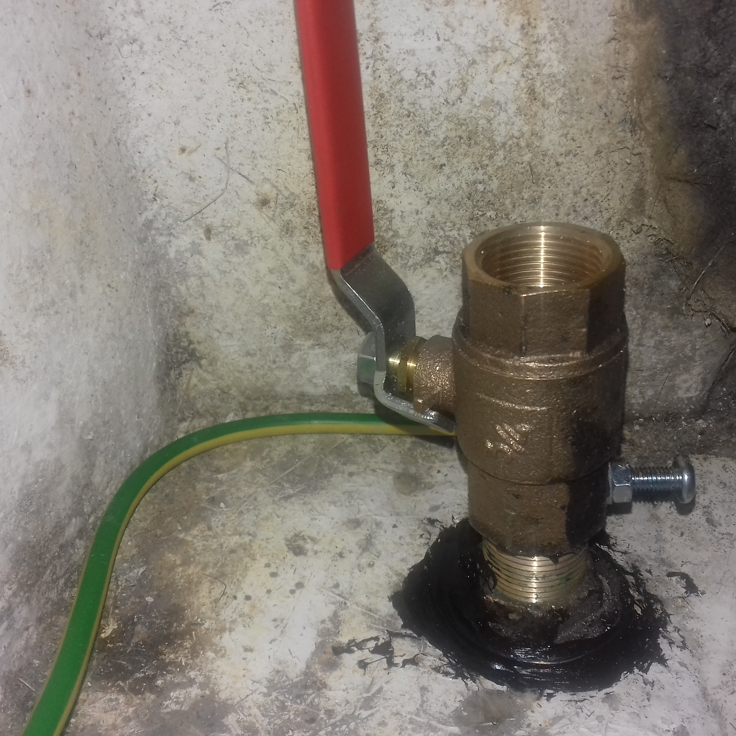
They look convincing when installed but I havent (yet?) measured the electrical resistance between the cable and either of the large bronze items. It has to be better than trapping a wire onto the body of the valve with a jubilee clip as was the case with one valve when I got the boat.
The other end of each cable was similarly fitted with a crimped and soldered tag and attached with a bolt to a copper common grounding plate under the head of one of the engine mounting attachment bolts. One of the cables from this plate is joined to the through hull anode mounting studs.
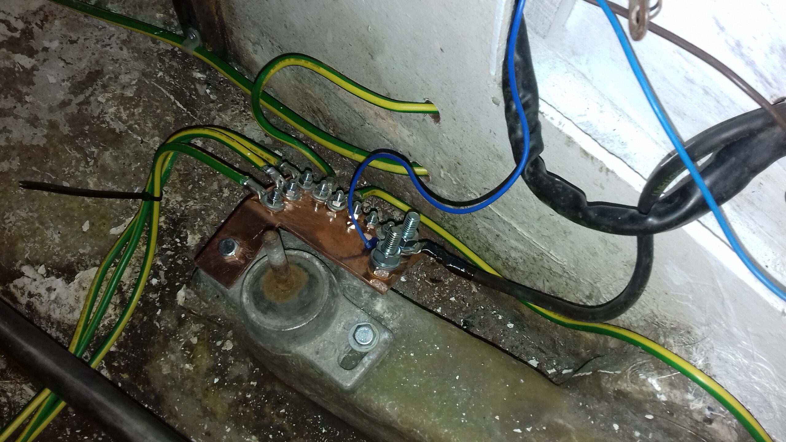 You may recall from the engine electrical post that I intended to attach the battery ground and engine electrical grounding wires (the big black one and the blue one in the photo) via this plate – Well that was not a good idea according to the advice on an American website about boat electrical issues. I moved all of those to an on-engine junction plate because it would provide the possibility of the battery causing massive corrosion. Any dampness near live wires could overcome your galvanic protection via a 12 or 24 volt leakage current and either destroy the anode or else wreck your “protected” metal fittings.
I mentioned earlier that there was more evidence to support having anodes within the hull. This is a somewhat later photo (23/2/2020) that includes the engine cooling seacock after I have had to deal with rain water getting into the engine compartment on several occasions.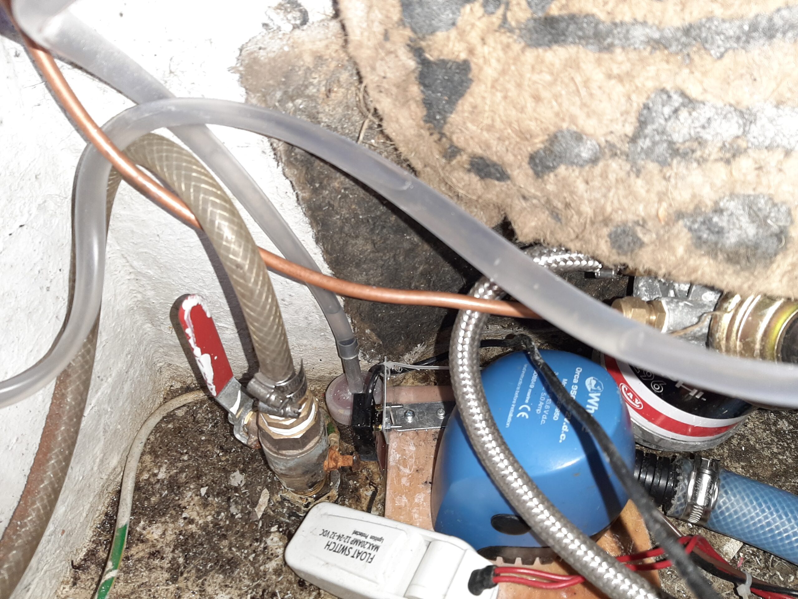 Other than the obvious addition of bilge pumps, fuel pipes etc., what is different from the first photo of this seacock (7/7/2018) and why?
The water in the engine bay means the whole seacock assembly has been wet and the steel bolt & nut have corroded. – That was the most anodic metal present in the pool of water that formed at the lowest point of the engine bay. So I think we need a zinc anode in this area to ensure that any standing water doesnt do damage in future. I obviously also need to replace that bolt and nut when I attach a slab of zinc.
Other candidate areas which collect water and contain metal that needs protection are the bottom of the galley cabinet (galley drain seacock) This connects under the floor to the end of the locker beside the table which is a lowest point in the hull). It also gets wet in the heads compartment (seacocks ) and the locker under the V berth in the fore cabin (connected to the chain locker but there is no other metal in that space).
On my boat there are encapsulated ballasts in the two bilge keels however they dont have any attachment bolts that enter the hull. I would definitely want to fit internal anodes to protect such bolts on any other boat where they were exposed to bilge water.
Lightning protection.
There is also a larger grounding wire (25 square mm / 100A) emerging from the plywood panel in the photo of the grounding plate. That goes from the anode through hull mounting rods to the mast base. Not a particularly straight cable run nor a low resistance one but hopefully enough to prevent any lightning strike causing lateral arcing within the boat or burning a path to ground through the hull. The general principle is one of helping by providing a conductor even if it is inadequate to handle thousands of amp current instead of the lighting finding it’s own way and damaging crew or hull in the process. Like the systems on buildings I want a path to ground if we are hit but not a good enough one to actively attract strikes to a high up grounded point. You might be aware that modern lightning conductor systems have about a 1cm gap in their grounding conductors to help with that so I am grounding the tabernacle rather than the mast and relying on the imperfect contact between the mast and the bolts to minimise attraction. As well as connecting the tabernacle to the anode, it is connected to the bow roller casting and the mooring cleat using similar cross section cables. The intention with that is to use the anchor chain or mooring to help with grounding to the water in the event of a strike.
Published 17/10/2020 but listed as 25/8/19 to get the order right.