Ok so this blog section is more about boat building rather than engines. Some of this I now about in theory from reading all those boat magazines and build your own boat books when I was younger. So here’s how this part is meant to look in a traditional wooden boat or a plywood speedboat.
 |
 |
|---|---|
 |
 |
So that’s the basic structure but from my perspective there is also quite a bit of making it work based on what was already present and the requirements of my particular engine.
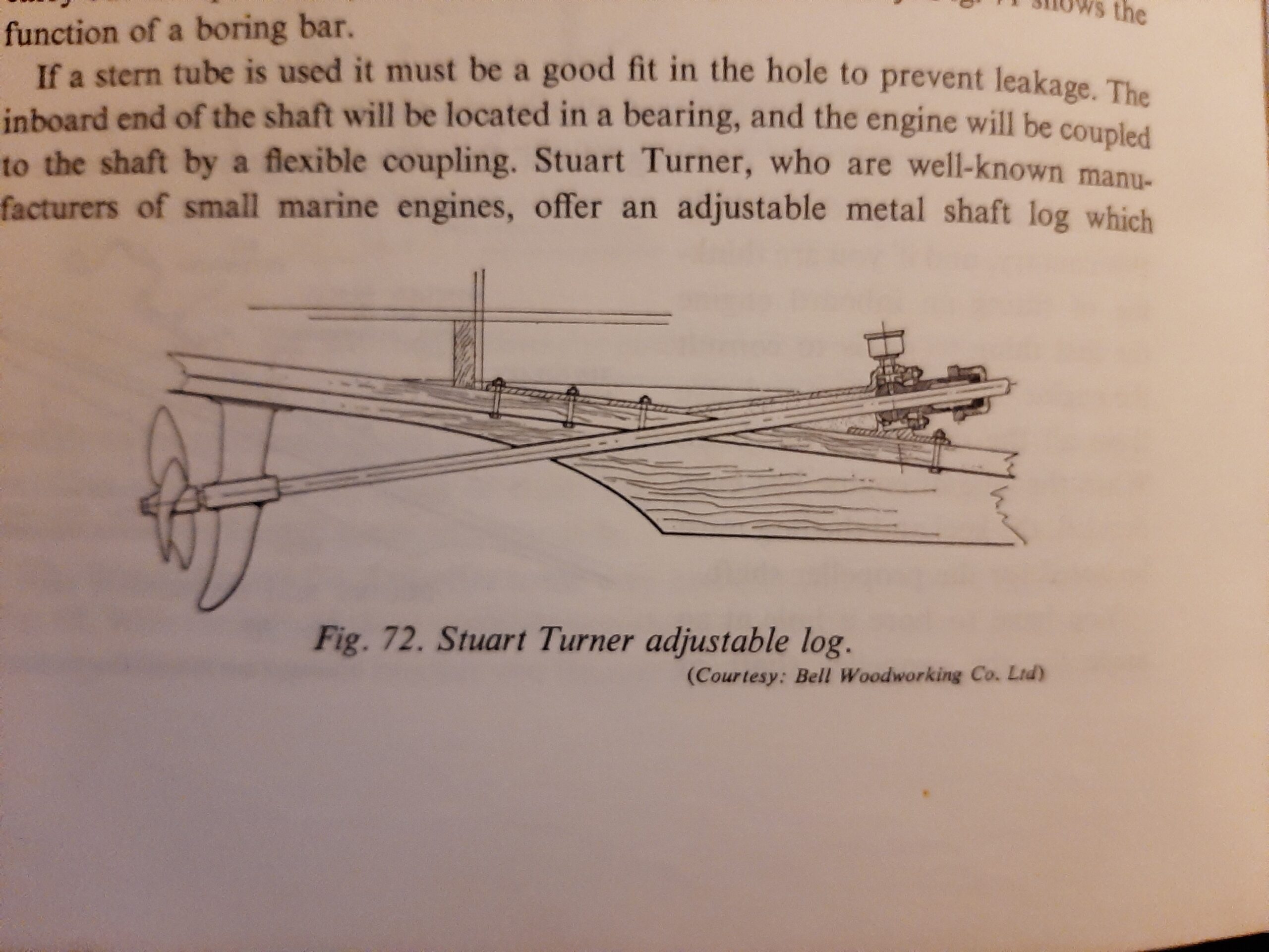
- Often the stuffing box may also take the thrust force created by the propeller That seems to be the case for the stuart turner example above). In the case of the Vire engine that is taken to the hull by the end bearing in the gearbox and the engine mountings so the shaft can be free to move in or out.
- In the top example above there is a tube with a stuffing box attached via a flexible rubber tube. This is the type of tube installed in Rathenice. This slightly reduces the need for accurate alignment of two bearings and the gearbox as the stuffing box can move in two dimensions to adapt to engine position without needing a pair of universal joints. My single universal joint is a reinforced rubber disk bolted to the output flange of the gearbox and a flange fixed to the prop shaft. The two flanges alternate in having their three bolts through the disk.
- In all of the examples above the tube or hole through the hull is open to the water and only sealed at the stuffing box.
If you already read the section about the first few days with the boat on the drive you might have thought I sounded over confident so lets see how it went –
Day 17 (Sunday 10/9/16) Investigated the state of the propeller, rear bearing and it’s stainless steel mounting piece. There are a couple of potential problems but nothing I am not confident I can sort out. Might not end up as the neatest solution to mounting a stern bearing but we will see what can be achieved. At the moment my main concerns are to work out the best way of attaching the stainless steel component while being able to ground it to the galvanic protection  (and probably the lightening conduction wires as well. This and the propeller seems like a useful area of metal to use as the exit to ground potential). All the propeller thrust is taken by the engine mounts so the attachment doesn’t need to be particularly strong. Maybe I can clean off paint down to the fiberglass and epoxy the metal onto that.
Tuesday 31/3/17 A couple of hours at storage spent trying to sort out the flexible part of the propeller shaft stuffing box. Looks as if it is either the original or someone later on has been using a lot of gelcoat. There was no jubilee clip holding the stuffing box into the hose section and the single clip on the hose to tube joint was rusted almost beyond recognition but embedded almost completely in white coloured resin. Managed to break off bits of solid rust to start removing the rubber but I think I will need to grind or ream out a lot of resin to be able to change the flexible part sensibly. The replacement is definitely getting 2 stainless steel jubilee clips on each of the joints.
Not tried dismantling it yet but the “stuffing box” appears to be a brass or bronze casing with two sealed bearings rather than the traditional compressed fibre and compression screw type. Brought it home for investigation and replacement of the seals / bearings. Will also have to work out a method of attaching the bronze tube and the stuffing box to the galvanic protection system.
Sunday 2/4/17 Over night I ordered the seals required for the prop shaft (http://simplybearings.co.uk/shop/Seals-Viton-Rubber/c19_4462/index.html).
Tuesday 4/4/17 Got the seals for the stern tube in the post today.
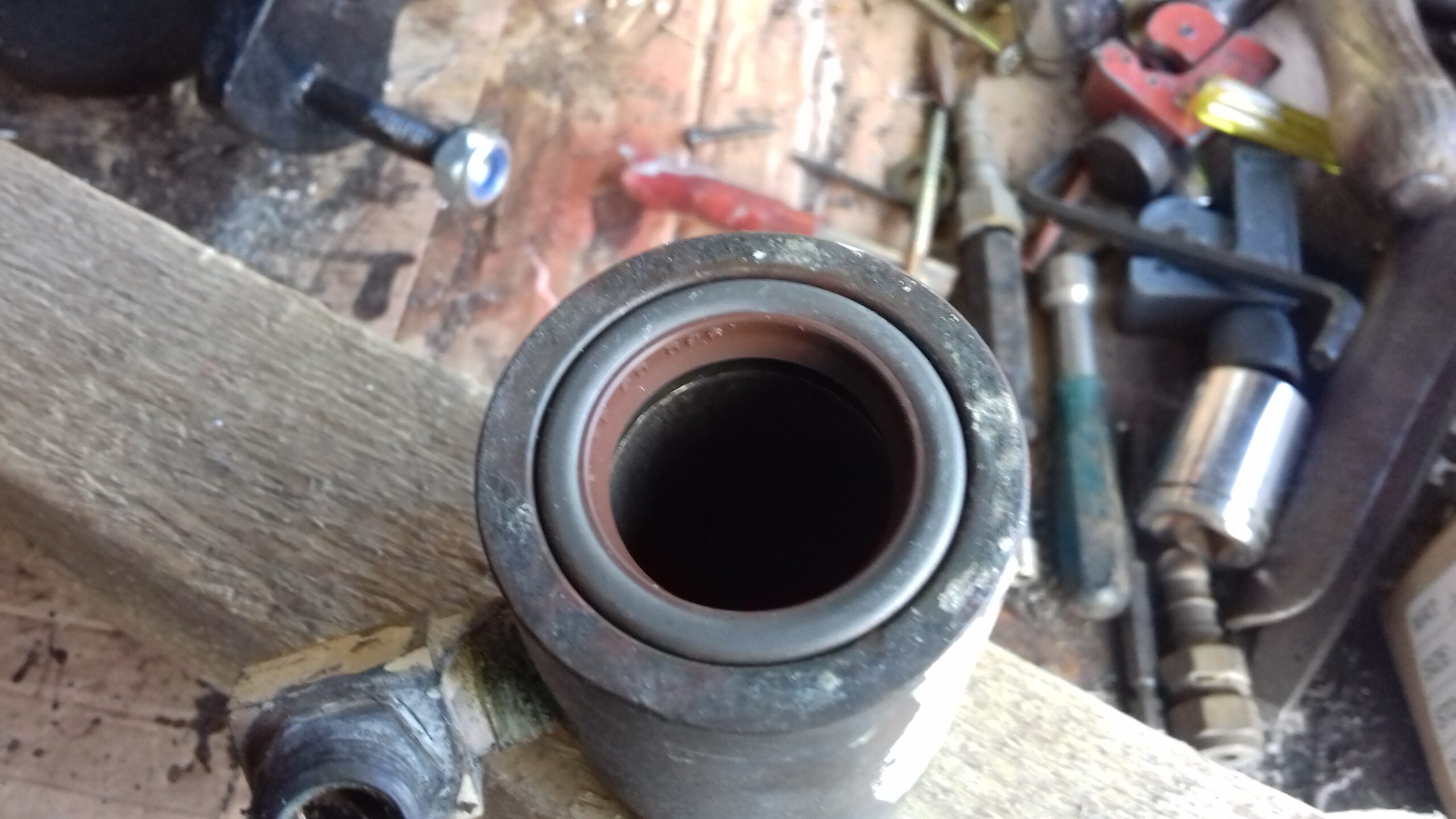
Saturday 8/4/17 Started off by tidying the garage a bit and fitting the new seals for the prop shaft. The original simple seals were in a bad way so couldn’t really have been used. 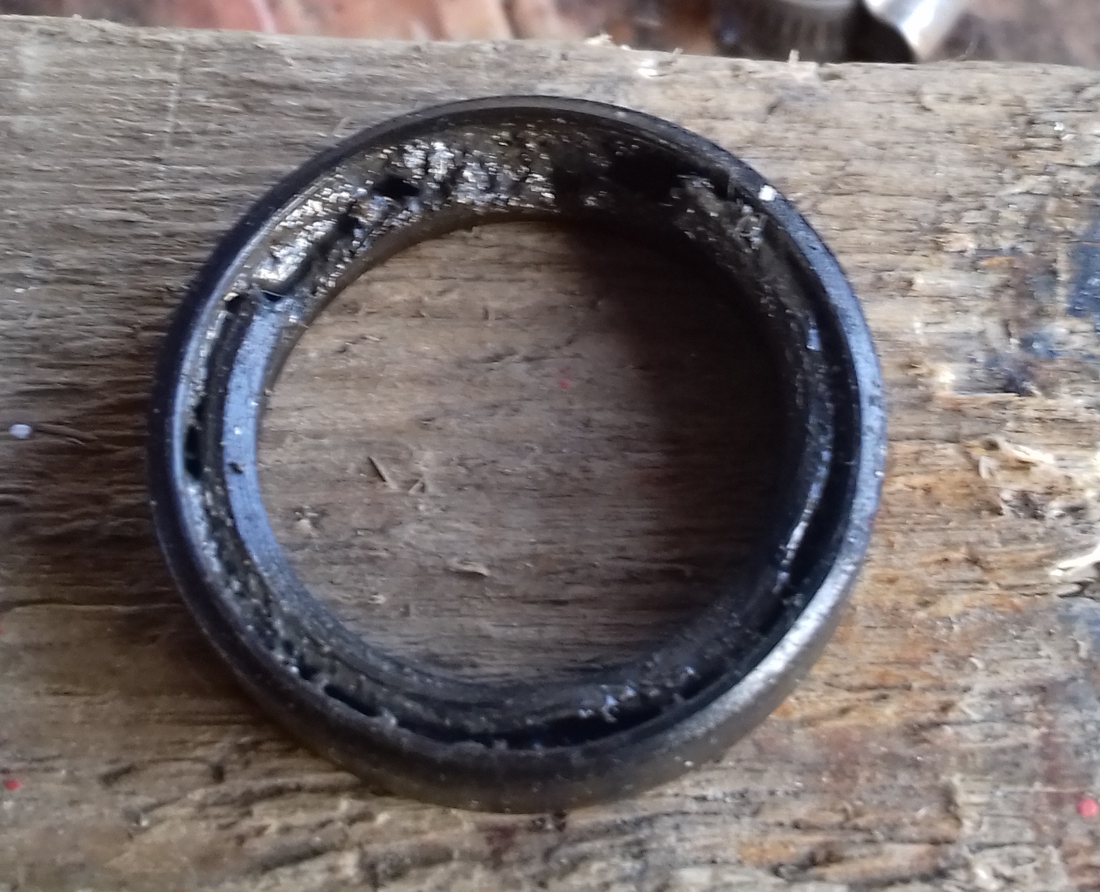 When I looked online the direct replacements were very cheap and were going to cost more to post than the price for the seals so no reason not to get something better.
The ones I bought have a metal casing and the sealing force is reinforced with a spring. Went in easily using the vice as a press and some cardboard to protect the rubber parts from contact with the jaws. Somehow I feel happier relying on two seals costing a little over £10 each to keep the water out of the boat rather than the £2 versions.

Wednesday 27/9/17 – Spent the rest of the evening trying to sort out the rest of a shopping list to get the engine ready to re-fit. I have a quote for the special stern tube rubber hose but I need window dimensions before ordering as it comes from the shop that will also do the rubber gasket to fit the glass / acrylic into the aluminium frame.
Thursday 22/2/18 The skin fitting and jubilee clips have arrived. Put together the tube and seals but I am authorising again tonight so no chance to fit this into the boat. I will also need to identify the thread on the universal joint so I can get a grub screw to lock it onto the prop shaft.
Friday 23/2/18 Stern tube seal assembly fitted onto the prop shaft OK but had to use a bit of paper wrapped round to help it through the seals. I haven’t fitted it to the tube yet as I need to ensure the shaft is properly centred while installing the cutlass bearing and also aligning the engine during re-installation.
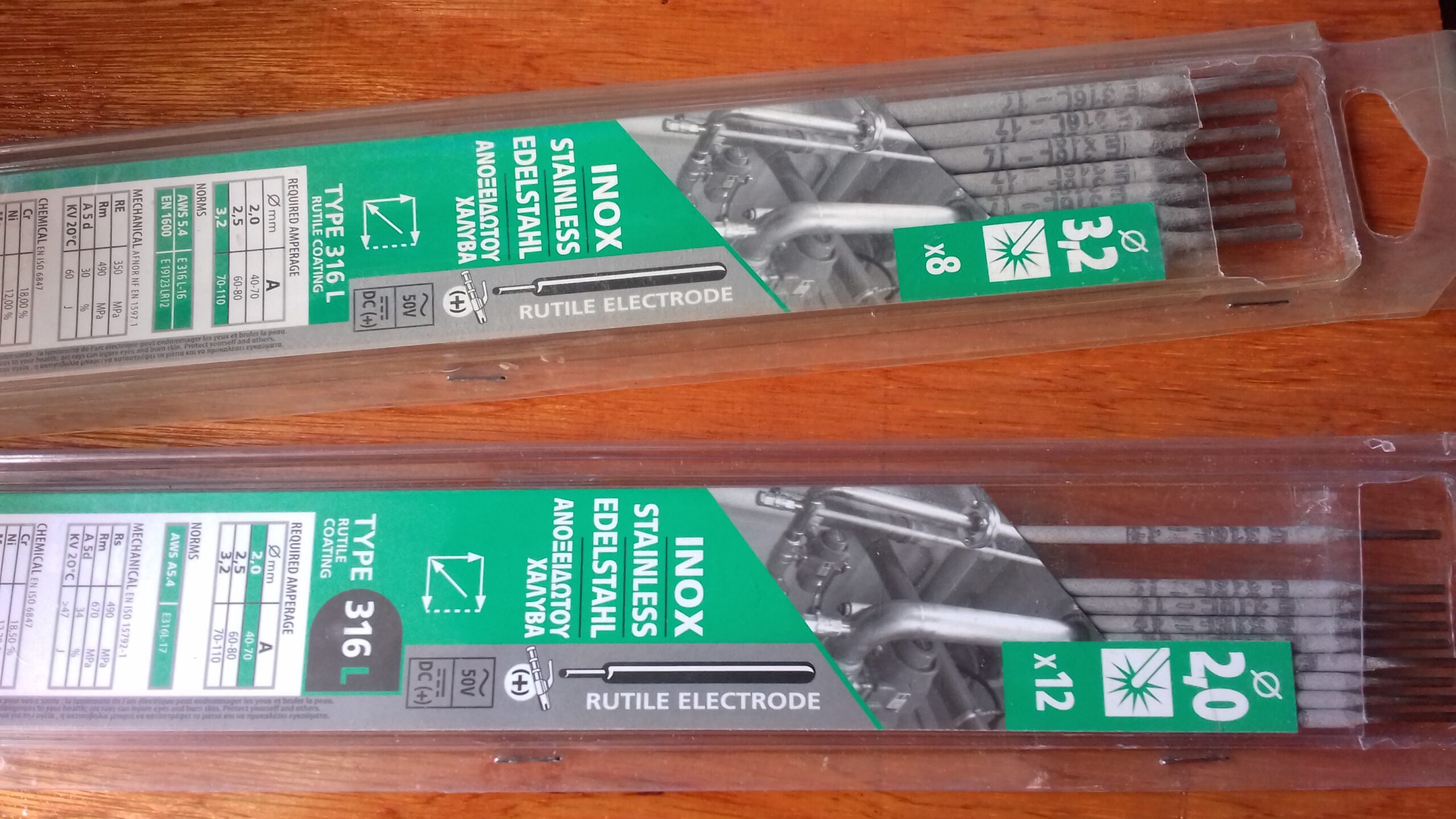
Saturday 7th April 2018 Woke at 5:45 and got up. After breakfast I tidied the bench a bit and got setup to weld the stainless steel bearing adapter. Turned out that it was just as easy to use the stainless steel electrodes as for the mid steel ones. Took three cycles of welding to do the job and I think the quality of the results was good. Those stainless steel stick welding rods are a great success as I found this welding session a lot easier than any of the previous ones and the welds look to me to be properly done. I needed to slightly bend one of the studs to get them parallel but the bearing fits well and the nuts can be tightened down with fingers. Needs a little cleaning up with the flap wheel but otherwise finished and ready to experiment with fixing it to the hull. 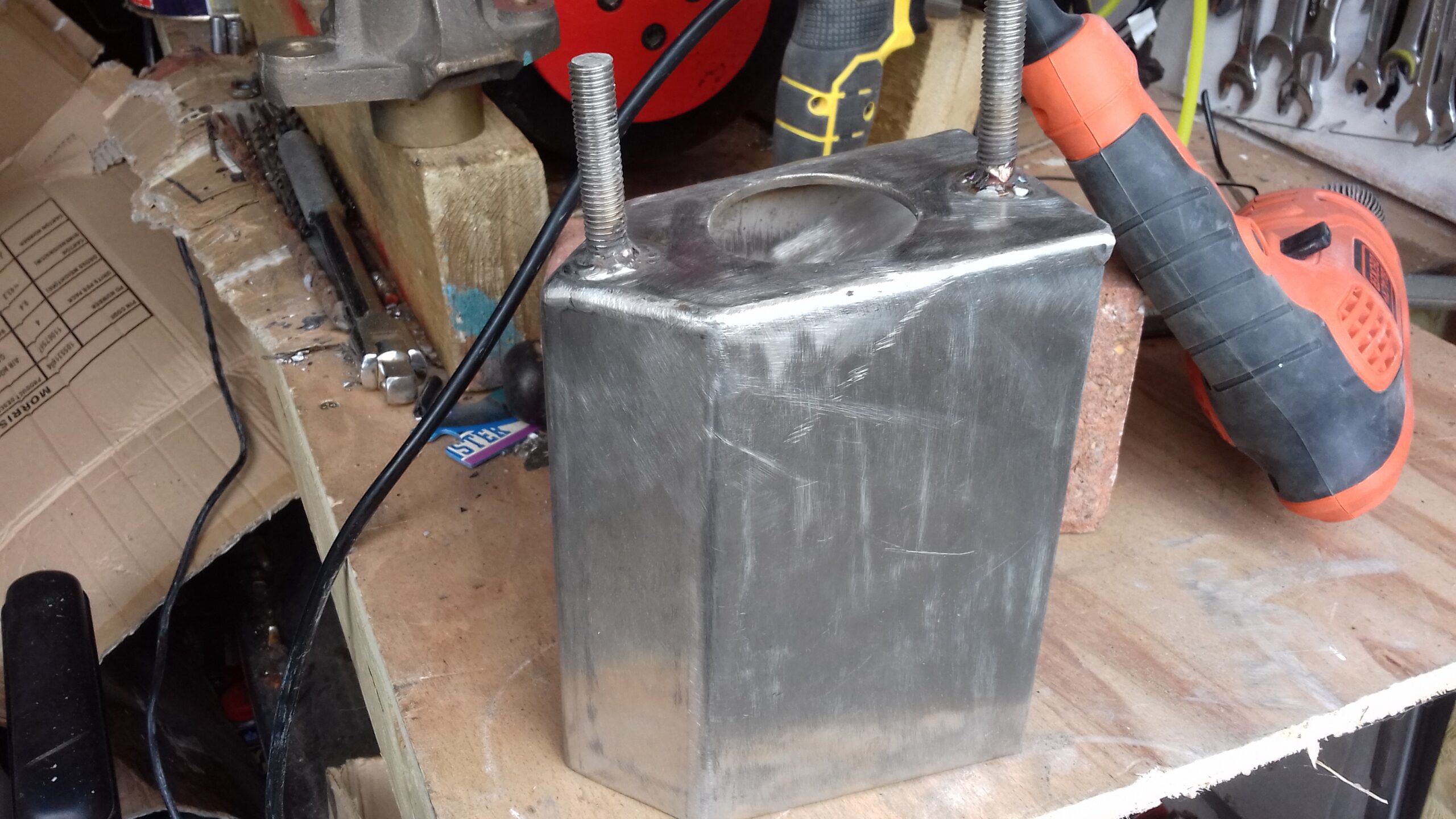

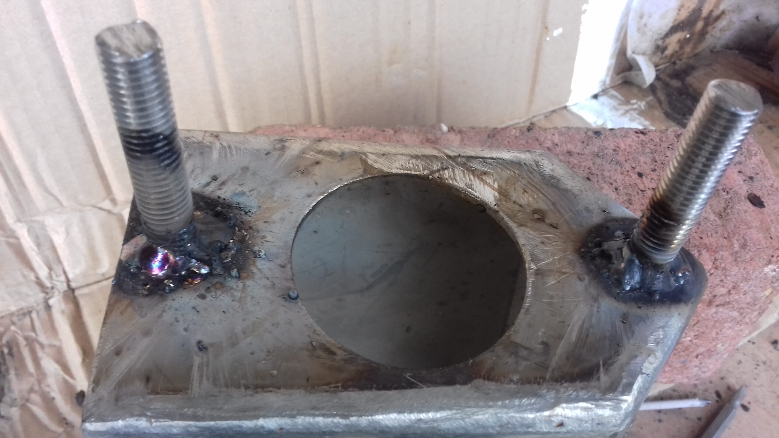

Cleaned up the cutlass bearing mounting device with the flap wheel in the mains electric drill. As well as removing flux and discoloration the wheel also slightly roughens the surface which will help the fibreglass resin to stick. I think I am going to get a small grinding wheel though so that I can make a series of deeper interlocking grooves on the inside to give some real grip. I cannot take credit for the design or construction of the box section as that came with the boat but the studs and fitting method will be all my own work.
Saturday 14th April 7:30 set off for storage to try to do some work on the boat. Fitted the prop shaft half of the universal joint. That means for the first time that we have all the components of the drive train put together ready to be aligned with the engine. Did a test fit of the bearing mounting system, it seems to be well aligned and I could have been tempted to try to fibreglass it onto the hull if it wasn’t for the large amounts of rain water running down the hull as a result of removing the cockpit cover. I also think it needs some holes drilling in the stainless steel and it’s inside roughening up with a grinder to try to make sure it is as well attached as I can manage.

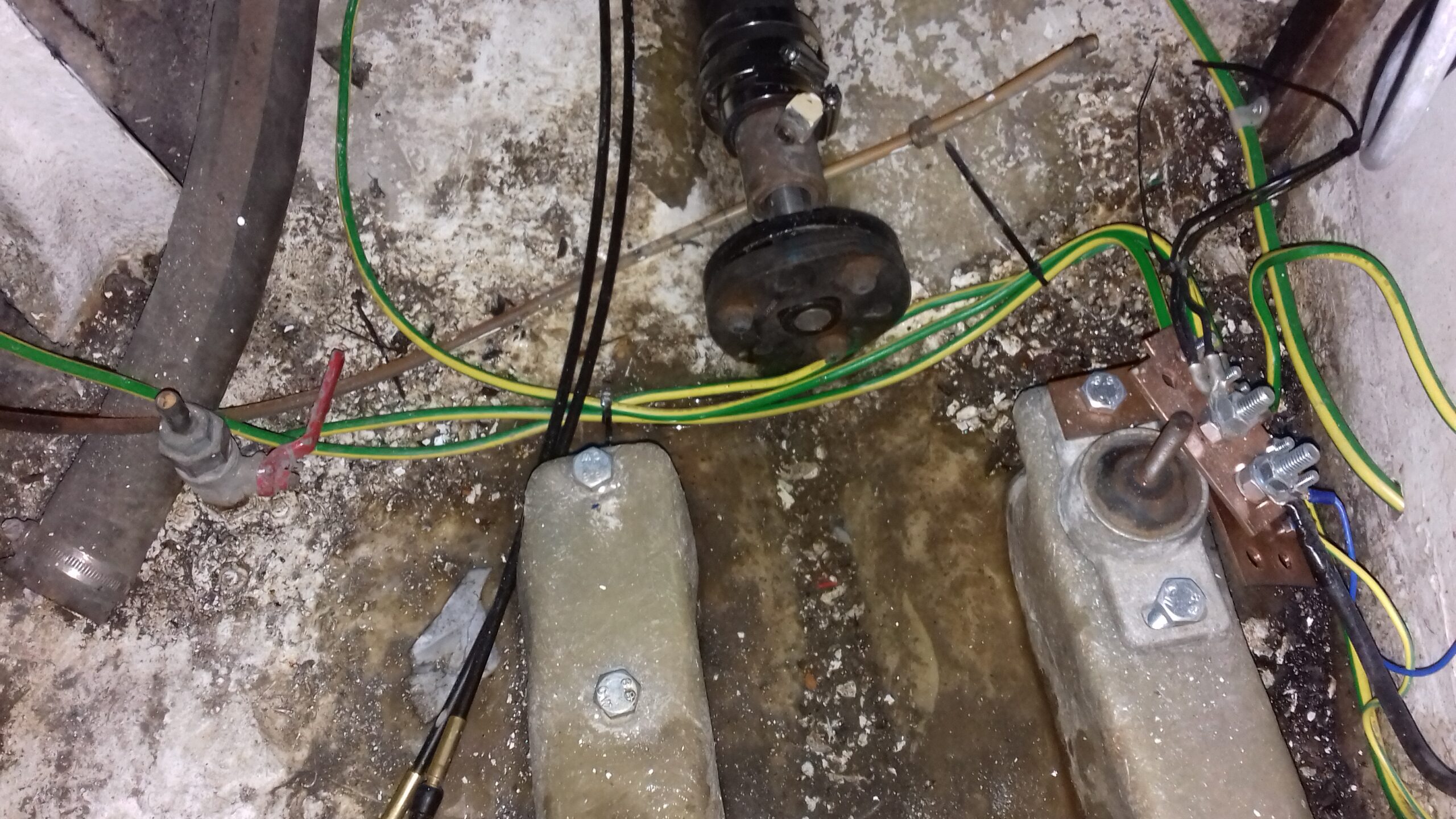
While there I did a rough dimension capturing exercise on the groove in the prop shaft for the propeller key. Easy to rub through this morning’s B&Q receipt with my fingernail so I have the width (1cm) and maximum permissible length (4.3 cm assuming it has squared off ends). Worked a bit like making a gasket as the paper was cut by the sharp machined edges. Now need to find the calliper battery to measure the depth of the grooves in the propeller itself and the shaft although there may not be much difficulty as the standard metric stock is in 1mm increments. The shaft seems to be made to metric dimensions as I don’t think the alignment of the lines with a plastic ruler would allow the true dimensions to be 9.5 mm (3/8”).
Cromwells list stainless key steel in the right width and either 10 or 8 mm thick (https://www.cromwell.co.uk/shop/materials-and-maintenance/key-steel/industrial-key-steel-metric/f/2939) so I may be able to source it locally with a 2 day lead time. They also have 5mm x 30mm A4 stainless steel coach screws (/product/p/QFT6332730C) and I have decided to use 4 of these to help attach the bearing adapter so it wont move if the fibreglass resin doesn’t stick properly. There should be plenty of room in the “deadwood” to position one from each side above and behind the stern tube and another pair forward and below, just a case of positioning each pair carefully so they are not close enough to intersect in the moulding.
23rd June Took the opportunity to make the key for the propeller. Sawn off 7cm and filed the ends to an approximate semicircle. Put that and the file in the car so they will be there when we go to storage.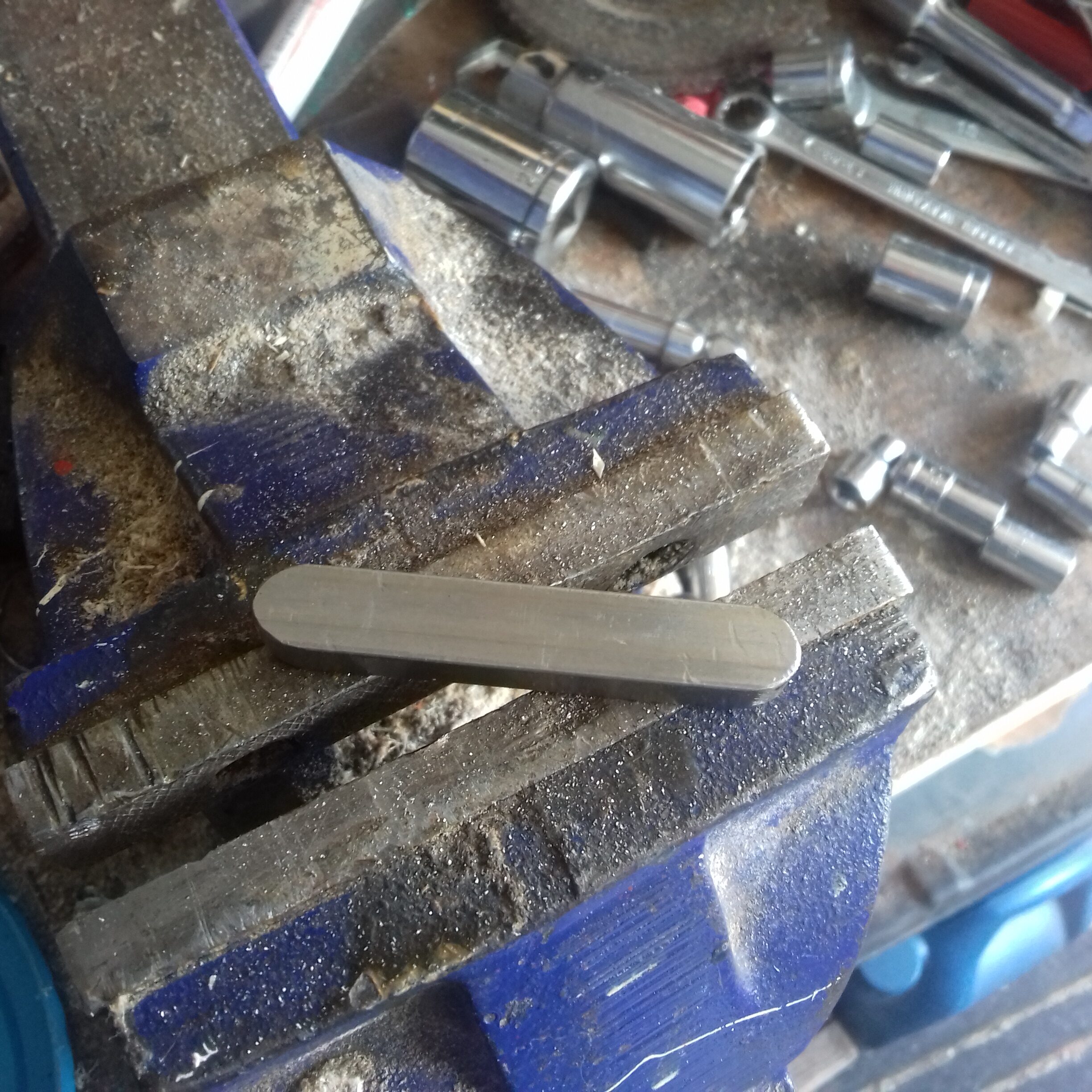
Saturday 28th June Checked the alignment and spacing for the cutless bearing and prop. As I now have several 5.5 and 6mm drill bits returned to the garage from Matt’s house, 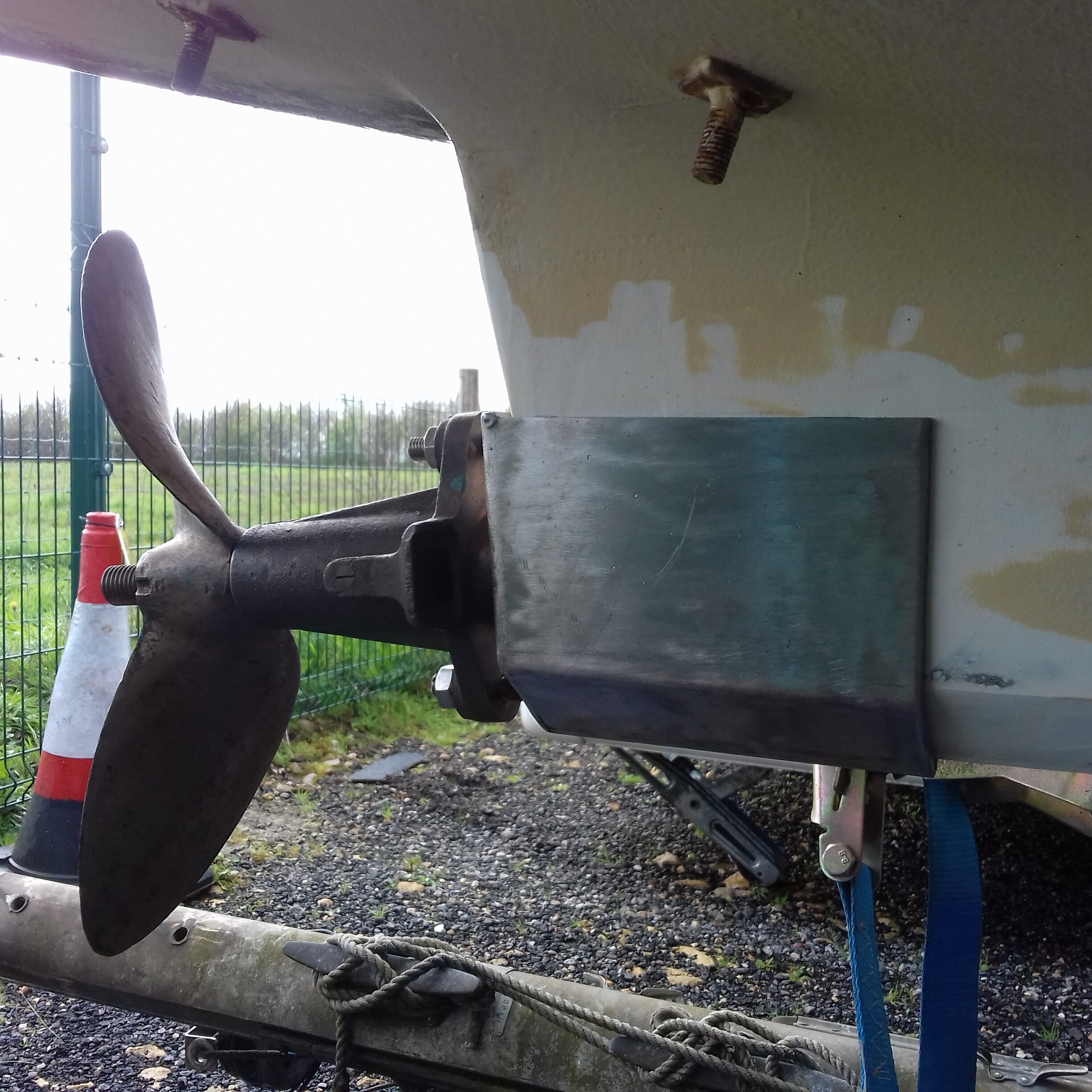 I can drill the holes in the mounting device ready for whenever the screws arrive. Then we just need another brief spell of warm weather so fibreglass will cure in a timely way and then I can install the mounting.
Sunday 29th June Drilled the 12 holes in the bearing fixing device. The screws from opposite sides will be spaced about 1cm apart in a fore & aft direction so wont clash or weaken what is a non-structural part of the hull.
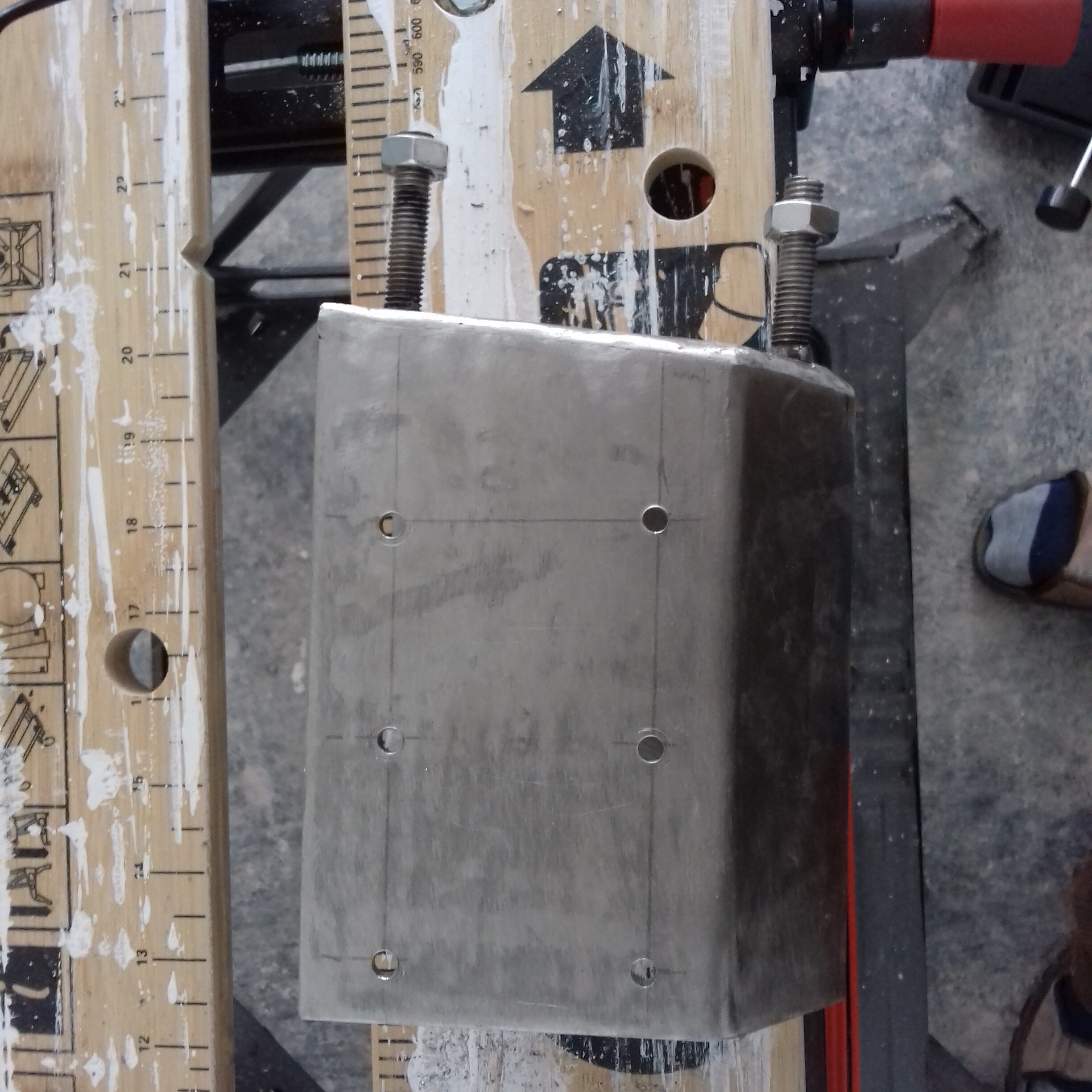
Needs a bit more work with the flap wheel and possibly a file to tidy up the inside where there is waste metal still attached round the holes but otherwise it is now ready to fit. I am impressed by the Black & Decker pirannah drills from a set we bought, they have two diameters so the smaller bit creates a pilot hole which the second diameter then enlarges to the intended size. Even without a centre punch mark the drills don’t wander about. The 5.5 mm one that I used made 12 holes through 3 mm stainless steel without lubrication and also without any obvious signs of work hardening. Helps that I was driving it with the battery drill in the lower gear setting but it is easy to get the right speed and produce proper spiral swarf under a situation where the normal drill bits make very little progress.
Saturday 30th June Early start on what looks to be going to be another beautiful summer day. Started off by sorting the garage a little and taking the extra 5mm off the length of the propeller key.
Sunday 1st July 2018 Now have the bearing mounting device installed. “Glued” into place with fibreglass resin (which cured frighteningly fast in 28 degree heat) and secured using the stainless coach screws that I bought. 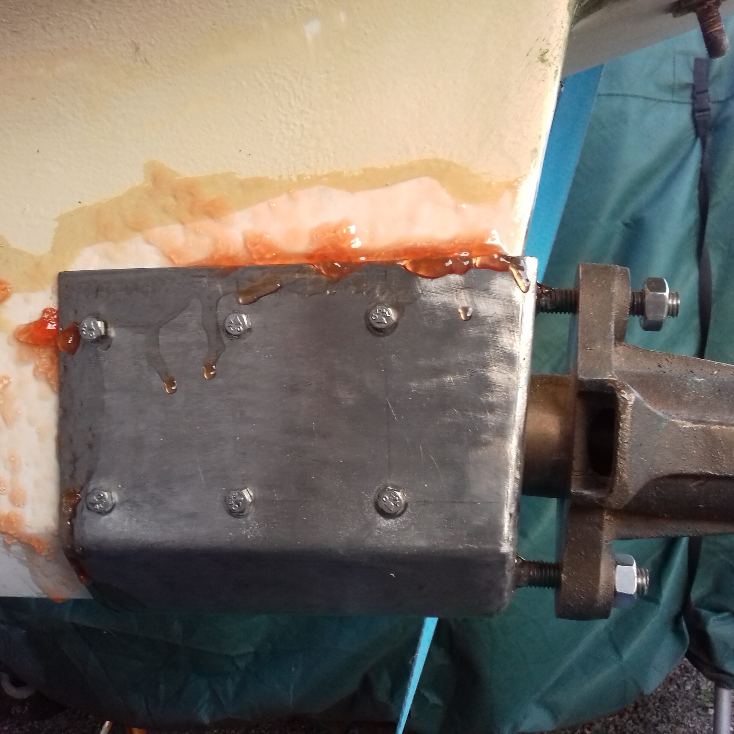 Will need the addition of some filler to fair it into the rest of the hull and a little attention with the flap wheel to remove excess resin. Also needs to be connected to the Zinc anode which goes onto the two studs sticking out of the hull. Still need to get the threads cleaned so that there will be a good electrical contact.
Trial fit of the shaft key was not as successful as it could have been – The keyway in the shaft seems to be either 3/8” (9.5 mm) or more likely 25/64” (9.92mm) rather than 10 mm as the key was not a 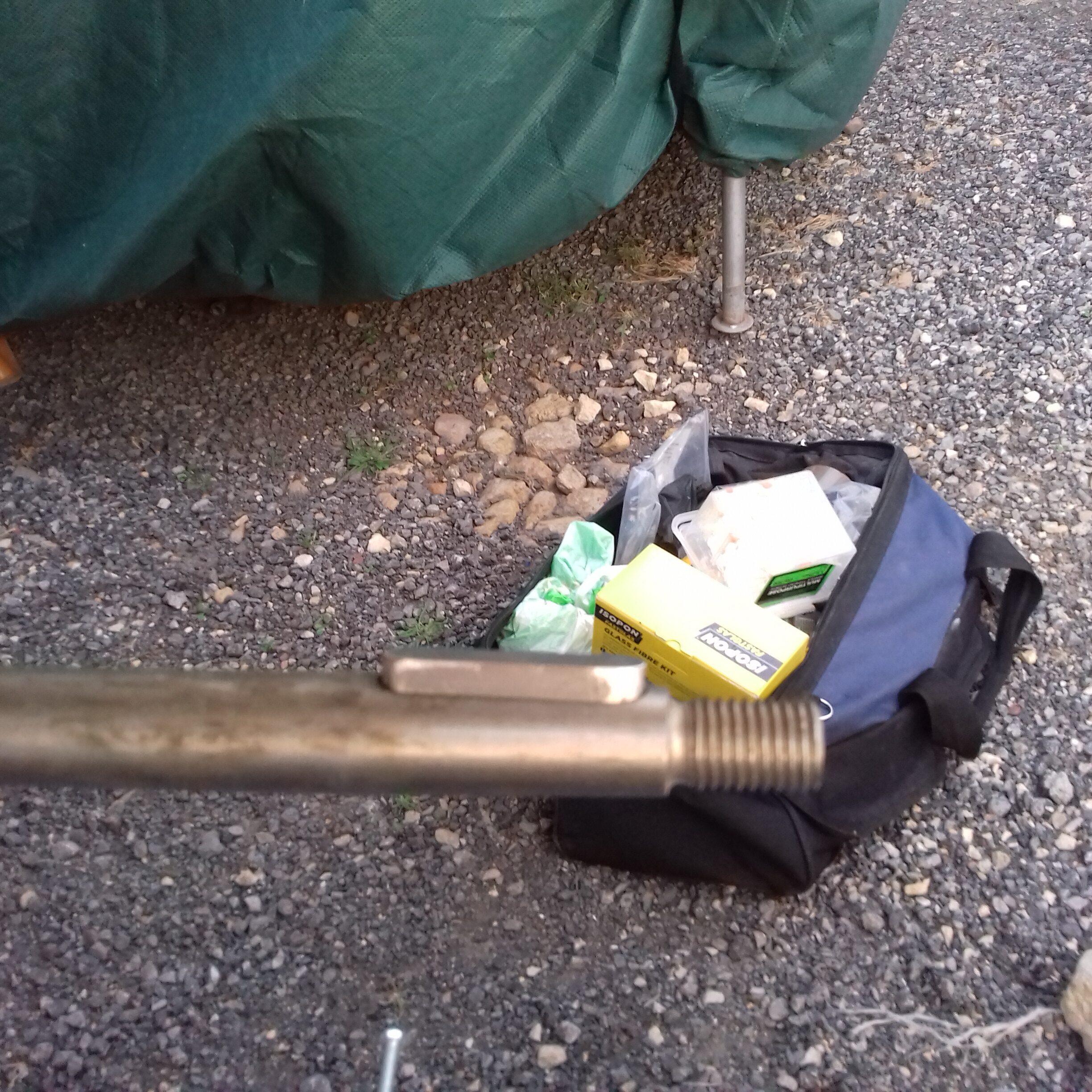 particularly good fit in the shaft. Also the 8mm thickness seems to be over size. I have brought the key and propeller home to file a little off the width and at least 1mm off the height of the key.
Tuesday 10th I added some more filler around the bearing mount. Not particularly neat at the moment but the warm weather means it sets really fast and there is not much time to spread and smooth it out. A bit of sanding will fix that before it gets painted. Probably a couple more work sessions to get filler on all the edges to fair it into the previous boat structure.
Saturday 20th July First job was to smooth out the filler around the  bearing mount. Quite a long job carving with the knife and sanding but done by 8:30. Needs a little more filler adding on the port side but that was not with me so will get done another day.
While in the sanding mood I also did a rather coarse sand of the transom. Need a little more filler in a couple of the holes at they didn’t sand completely flat. Ideally I would like to get a couple of coats of undercoat on the transom before fitting the other rudder pintle and the outboard bracket back on. Only urgent because those two jobs need doing before the engine can go back in.
Saturday 28/7/18 One last hoover in the engine bay which still didn’t clear out all of the damp rubbish between the engine bearers and the stern gland. As a consequence I didnt paint that particular area but did  do all of the hull as far back as I could reach easily. The slope of the hull and limited height makes it a bit awkward with a full size paint can so the last bit and the inside of the transom will be easier to do as a separate job once I have a smaller container to put paint in. Certainly looks a lot cleaner and ready for use after that painting session.
Just 4 jobs remain before the engine can go back in including at least one more trip back under the cockpit after the paint dries. –
- Fixing the gas pipe to the bulkhead and underside of the cockpit sole (Need the screws to fix the brackets).
- Fixing down the exhaust box.
- Painting the water pump.
- Attaching the engine ends of the cooling water hoses.
Saturday 4th August (Day 710) A big piece of progress today even if it is only a few minutes work to achieve. The engine went in with relatively little fuss although the weight of it and the rather restricted 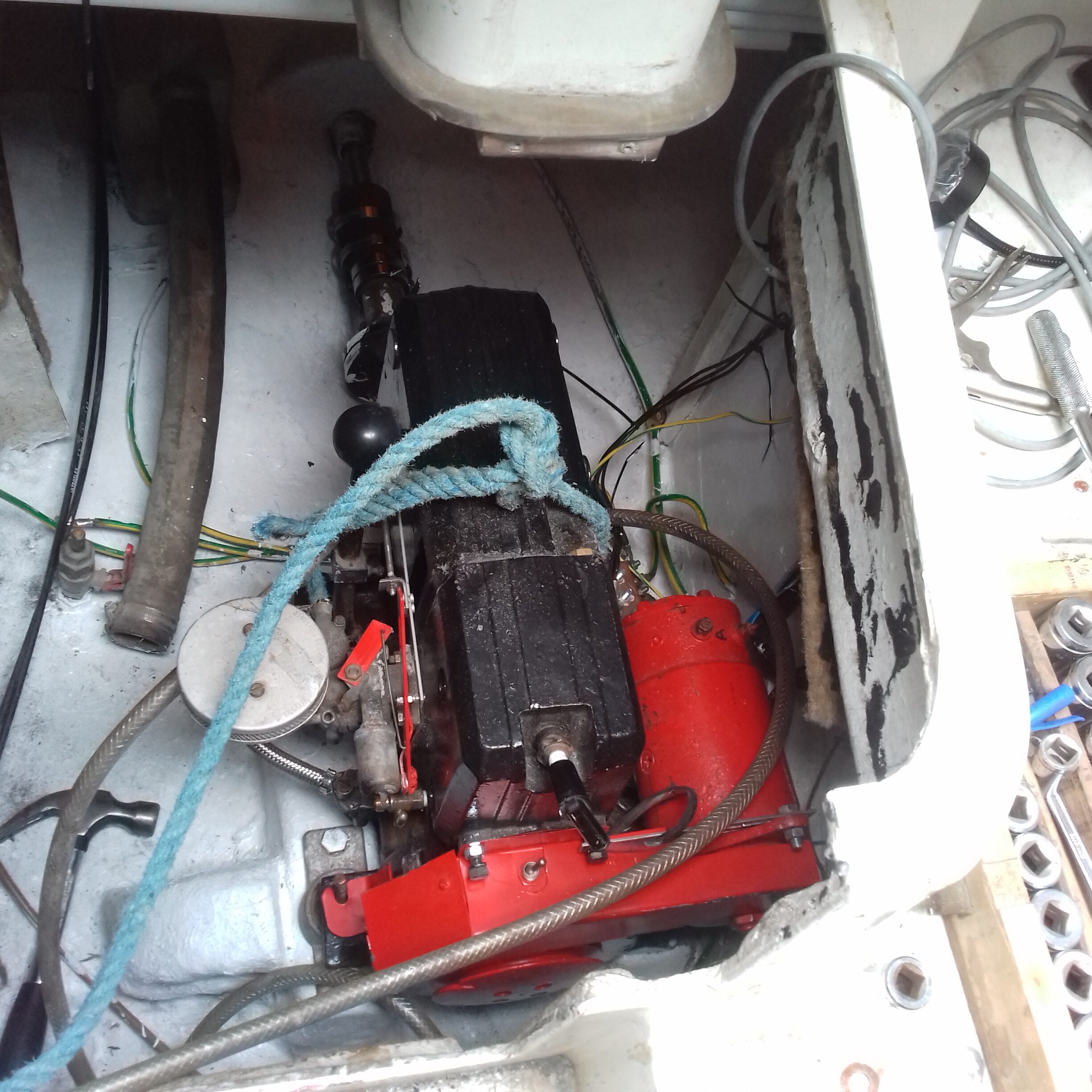 space around the dynastart meant it was a little fiddly getting it onto the mounting studs. Next time I go to the storage I will be adjusting the alignment which will probably mean multiple cycles of lifting the engine off the rubber mounts, changing packing washers and then lowering it back down. At the moment I have no idea how close it is to proper alignment so don’t know if it will take only a short time or several days to get it right.
Once the alignment is done it shouldn’t take more than an hour or so to connect up the controls, electrics, cooling plumbing and exhaust systems.
Sunday 5th August I had managed to file off a lot of the excess metal from the prop shaft key and also sort out other items that need to go to the boat but then left the box at home when we went to storage.
Also retrieved the bronze bolts from Laneham close. Definitely don’t understand how they can have sent two previous orders to our current address but then used the original delivery details for my fourth order. It should be fairly quick to replace all seven of them next time I am at storage.
Saturday 11th August Started off by trying to get the engine aligned with the prop shaft. As things are positioned at the moment the shaft rubs against the port side of the stern tube. Although I moved the mountings in the 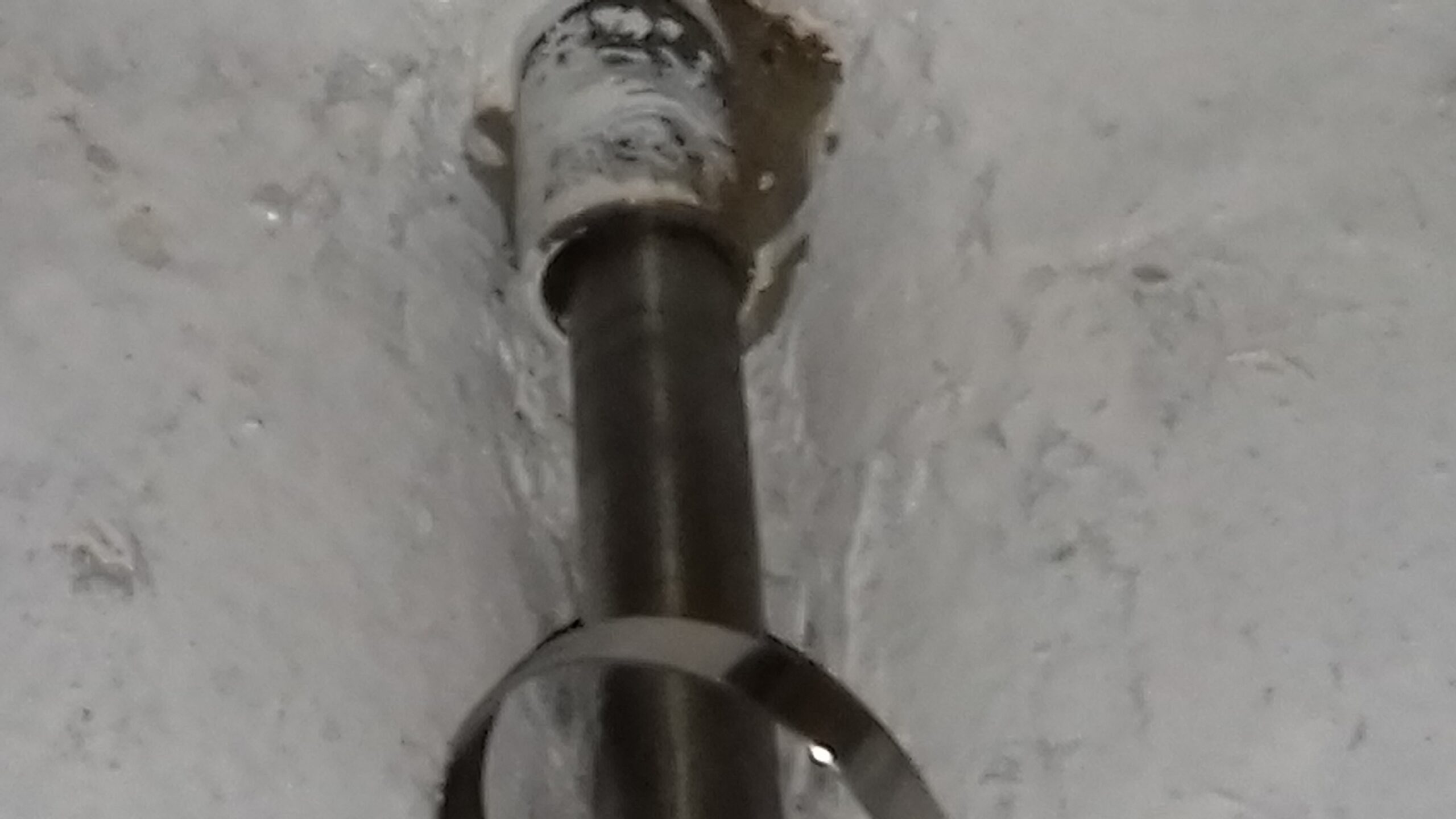 right direction to move the prop shaft more central none of that made any difference. Eventually realised there is a fundamental problem in that the fibreglass
 reinforcing on the engine bearers means that there is no space for the larger cross section of the engine where it joins to the gearbox.
Once we get a generator organised I will have to grind off something like 4 mm from the starboard side bearer to let the engine vibrate on the rubber mountings and also move the required mm or so to starboard. That needs doing for a lot of the distance between the aft mounting to the marker pen line. As the engine was in the space when I brought the boat home I wonder whether this was a problem with the previous work done by Dave and may have contributed to him giving up working on his own boat.
Having made no progress with that part of the job list, I sorted out the propeller key instead. Took a fair amount of filing to get the key thin 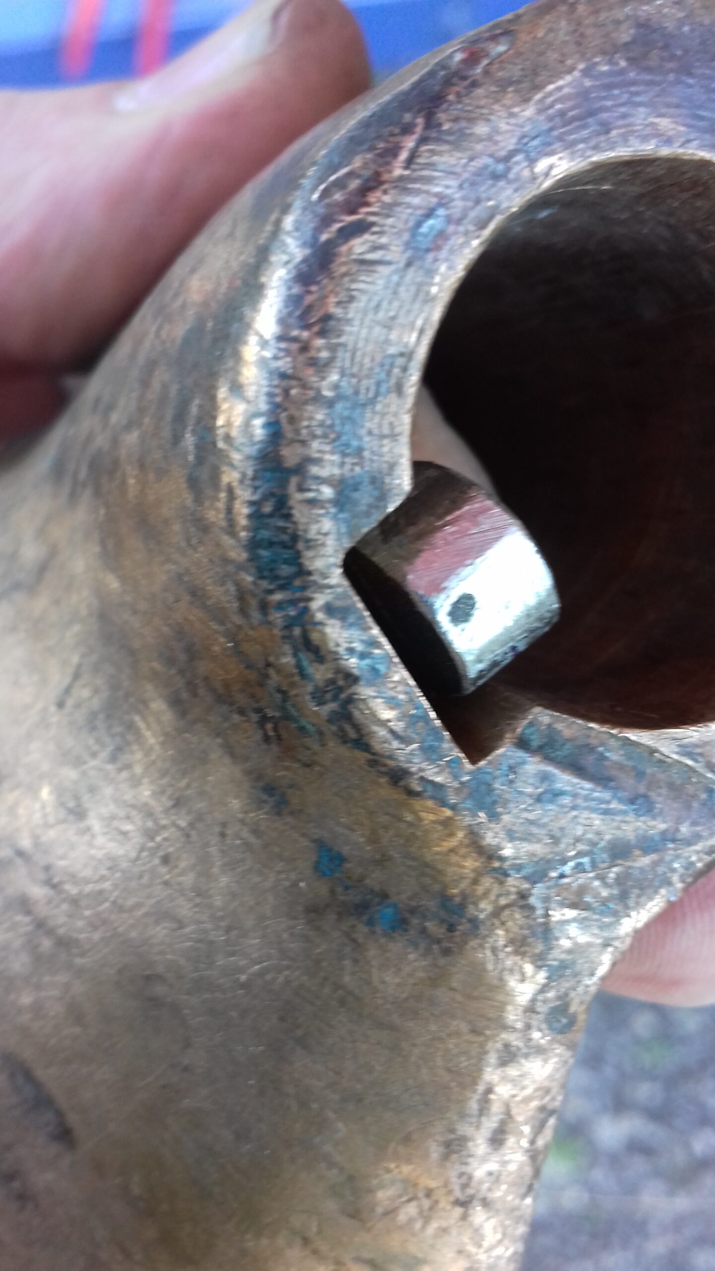

enough to let the propeller fit anywhere close to the position it achieves with no key. To start off the key would rock in the groove on the prop so the first few minutes were spent filing that part of the combination flatter. Then worked on getting the key thinner so the prop could slide further up the taper on the shaft. Might need a little more work eventually but is now easily put on and achieves a location only a few millimetres away from the no- key position. This problem with the propeller hub also makes me wonder whether this prop and shaft were functioning properly on the boat before it went ashore and stayed there.
Thursday 14th While I was at storage working on Horsebox conversion, I also painted inside the stern bearing holder, then installed the cutless bearing and prop.
Tuesday 4/9/18 Two trips to the boat this afternoon and evening with tea in between. Worked out the best way to do the engine alignment and realised it is made really easy because of the long threaded studs on the engine part of the flexible joint. Added a nut and washer to each of them so you can tighten each one hand tight and then rotate the output disk – If the washer becomes loose as it turns then that part of the rotation has the engine disk closer to the stern and the engine needs to be moved.
I think I need 3 washers on each of the forward mountings and none on the rear ones. Lifted the engine off the mountings and added those washers. Need to file off a few millimetres of fiberglass from the starboard bearer so not as big a problem as it initially appeared. Once that is done the engine should be free to move to the side a little (although it seem lifting the flywheel has already allowed the shaft to move a little away from the port side of the tube) and can be tightened down if the positioning passes the test.
Also sorted out the fuel solenoid indicator which had not been working (LED negative went to the switch panel and was not actually connected to battery negative).
Friday 7/9/18 Several cycles of lifting the engine, adding washers as packing under the forward engine mounts, lowering it back and checking the alignment. Seem to be about as close as we can get although there might be one more washer than absolutely needed.
Saturday 8/9/18 Early start because the dogs were fussing and then I couldn’t get back to sleep. Got up, had breakfast and I was back at storage a little after 7:00.
Sorted out the on-engine wiring for the choke and stop switch, bolted down the electrical grounding plate and sprayed everything with water protection lacquer.
Dynastart drive belt is a little too long so the casing ends up in contact with the plywood bulkhead between the engine and electrical bays. I estimate that the belt should be about 2” shorter so as a first try I have ordered two SPZ762 belts to try in place of the original SPZ800 belts.
Would you believe that there was almost exactly no progress with the boat from October through to February? Well we did almost entirely renovate Matt & Annabel’s house, progress with horsebox conversions and the Camper van because those were indoor jobs with available electricity. Any time I did spend at the boat was mostly used to bale out the engine compartment and cabin or re-organise slipped tarpaulin covers.
In that time I also managed to almost totally wreck the main camera lens on my phone. The photos that follow are therefore very poor up until I got a new phone.
20th January I also made the mounting bracket for the Battery Isolator cover – There was a slight redesign while marking it out as I 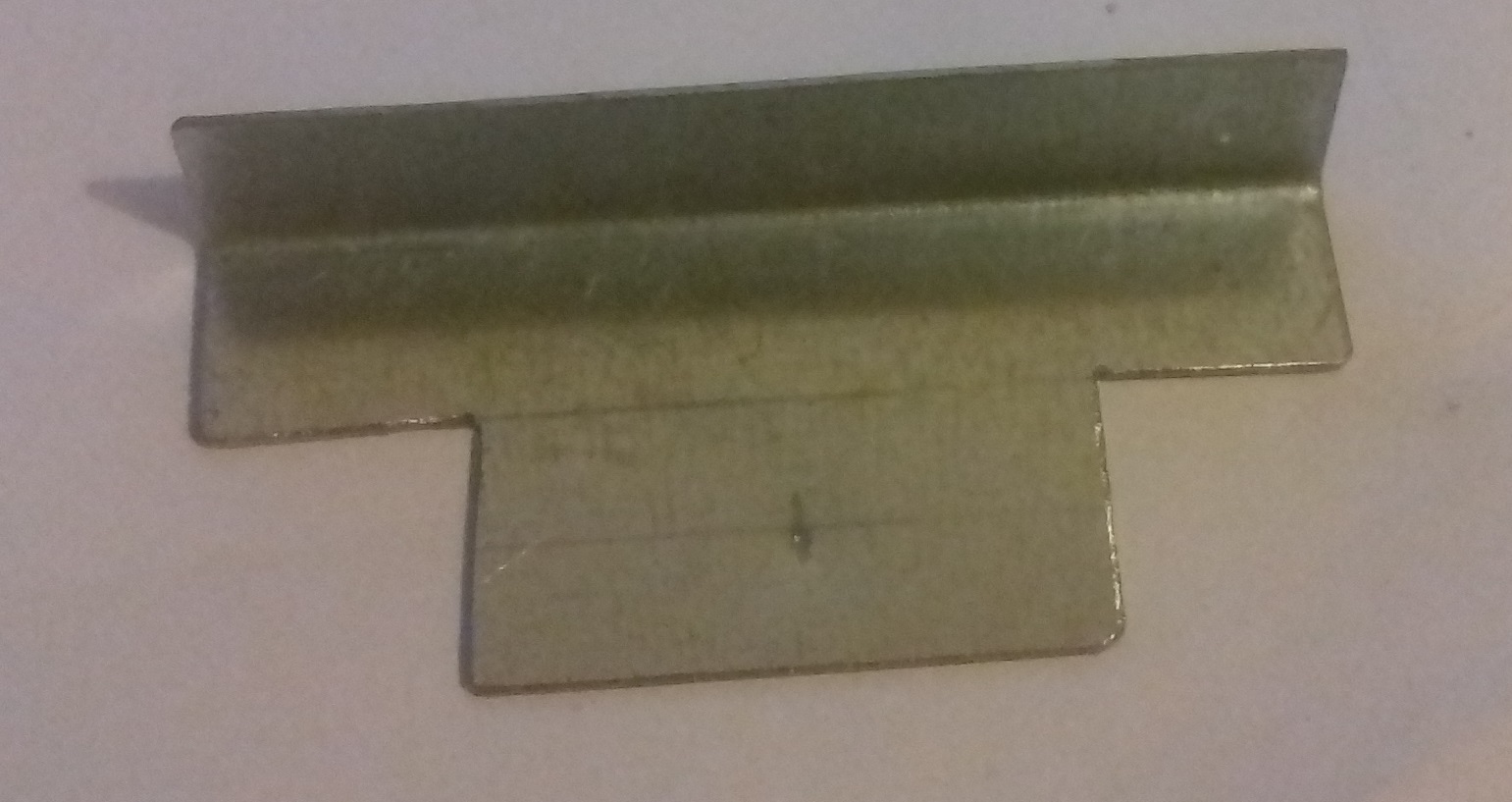 was not convinced the 1cm angled part was enough to extend beyond the curved part of the switch cases so I made it 1.5 cm on both sides of the bend but kept the distance from the bend to the threaded rod the same. Again this is not yet finished and needs me to find the right size threaded inserts before I can drill, crimp and paint. Also may need to make adjustments when I try it with the switches.
Sunday 3rd February Most of the afternoon was spent filing out locking cams for the camper van sliding door – The original is a complex machined aluminium casting most of which was missing. These are almost unavailable for right hand side doors (which are by far the most common) but are rarer than hen’s teeth for left hand side doors and of course these are a mirror image of each other. My trial and error developed version has two steel cams, one which controls the sliding part of the motion as you open the door and the other which unlocks as the door is almost closed and allows the rear “hinge” to rotate the back edge of the door into the closed position. This is typical of the challenges I end up taking on instead of progressing simple tasks on the boat.
Having made and spray painted the cams I went on to drill out the boat electrical cover mounting hole, crimp in the 5mm threaded fixture 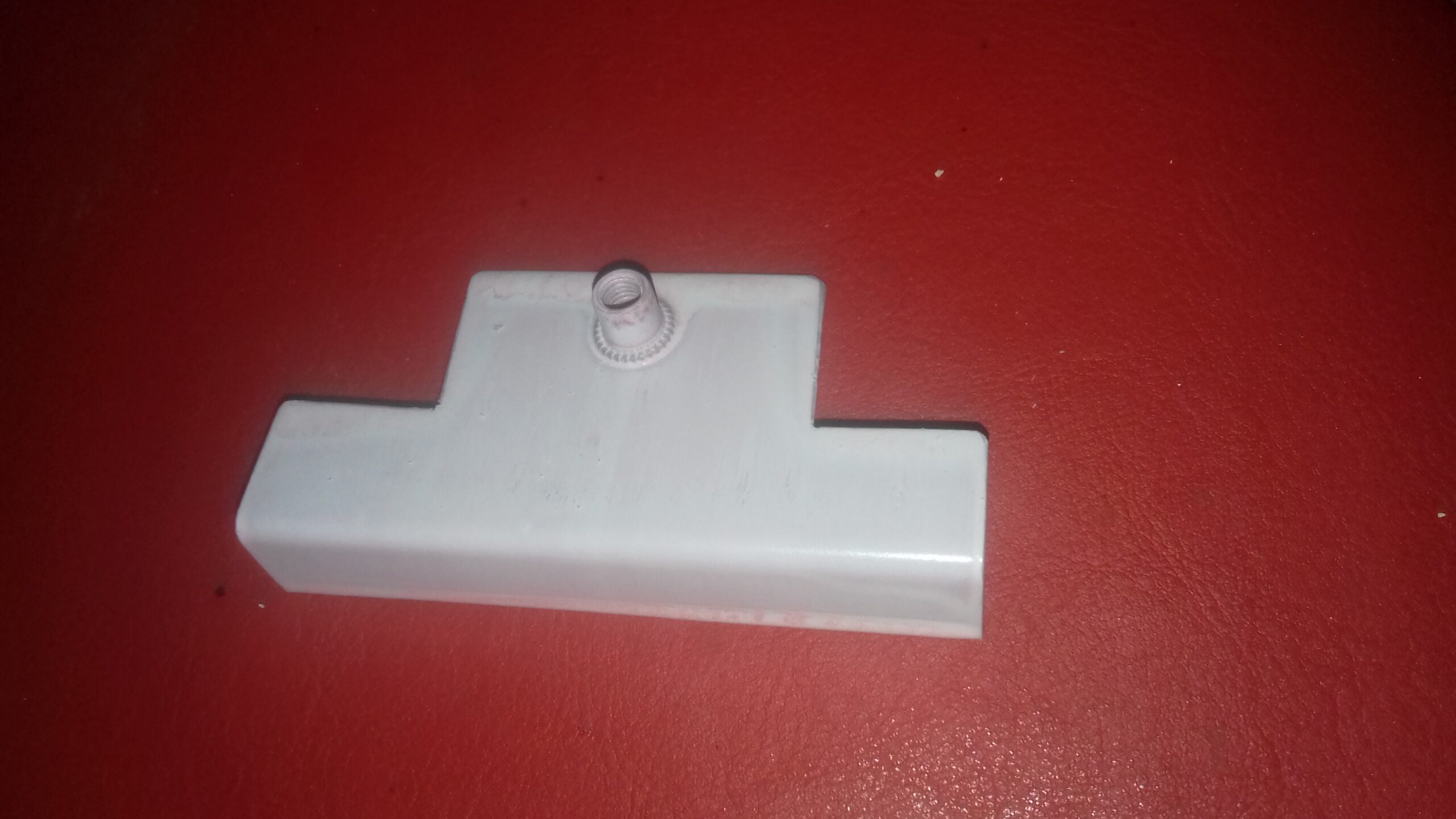 and then paint the hopefully finished bracket. Next phase of that will be to take it to storage, try it in position and then drill the cover for the screw. Nor sure yet whether I will use the straight slotted machine screw, a conventional set of nuts or a wing nut to secure the cover. The battery switches are rather close to the engine electrics panel so it rather depends on how long the threaded portion needs to be and whether or not the screw is able to work loose in the crimp fitting.
Sunday 3/3/2019 We were supposed to be handing over the horsebox but for the second time Matt has not heard anything from the purchaser so I went to storage to work on the boat!
Not too much water in the hull so I left it and concentrated on finishing off two long standing jobs –
- Ended up cutting two pieces of threaded rod to fix the battery switch cover because although the original piece was about 3cm longer than required, I couldn’t get it to line up when I screwed it into the bracket and tried to thread it into the cover. A longer piece did the job when I could thread it through and see to line it up when screwing it into the bracket. The extra is a bit of a potential snagging point as it sticks out a couple of inches and it will need a neat (and less sharp) end if it is staying. Might be able to do something neater once the wires are all settled in their final places so patience may solve the problem.
- The fuel hose is in place so we now have the completed system from the locker to the carburettor, just need the tank and coupling hose. I
 am not convinced the crimp onto plain walled fuel pipe at the filter is particularly robust as the pipe seems to rotate even though all the fittings are done up. Just one of the joints that I will need to keep an eye on until I know they are leak proof. Probably also worth glassing in a wooden block so I can screw down a pipe clip and ensure the fuel line doesn’t get mixed up with the flywheel.
No time to make progress with the cooling water plumbing but I might get a chance on one of my days off.
Tuesday 12/3/19 Frustratingly I had finally received my parcel today but I left the other bits at the boat yesterday so couldn’t even assemble the hose adapter into the bronze bush. It would only be 10 minutes work but would 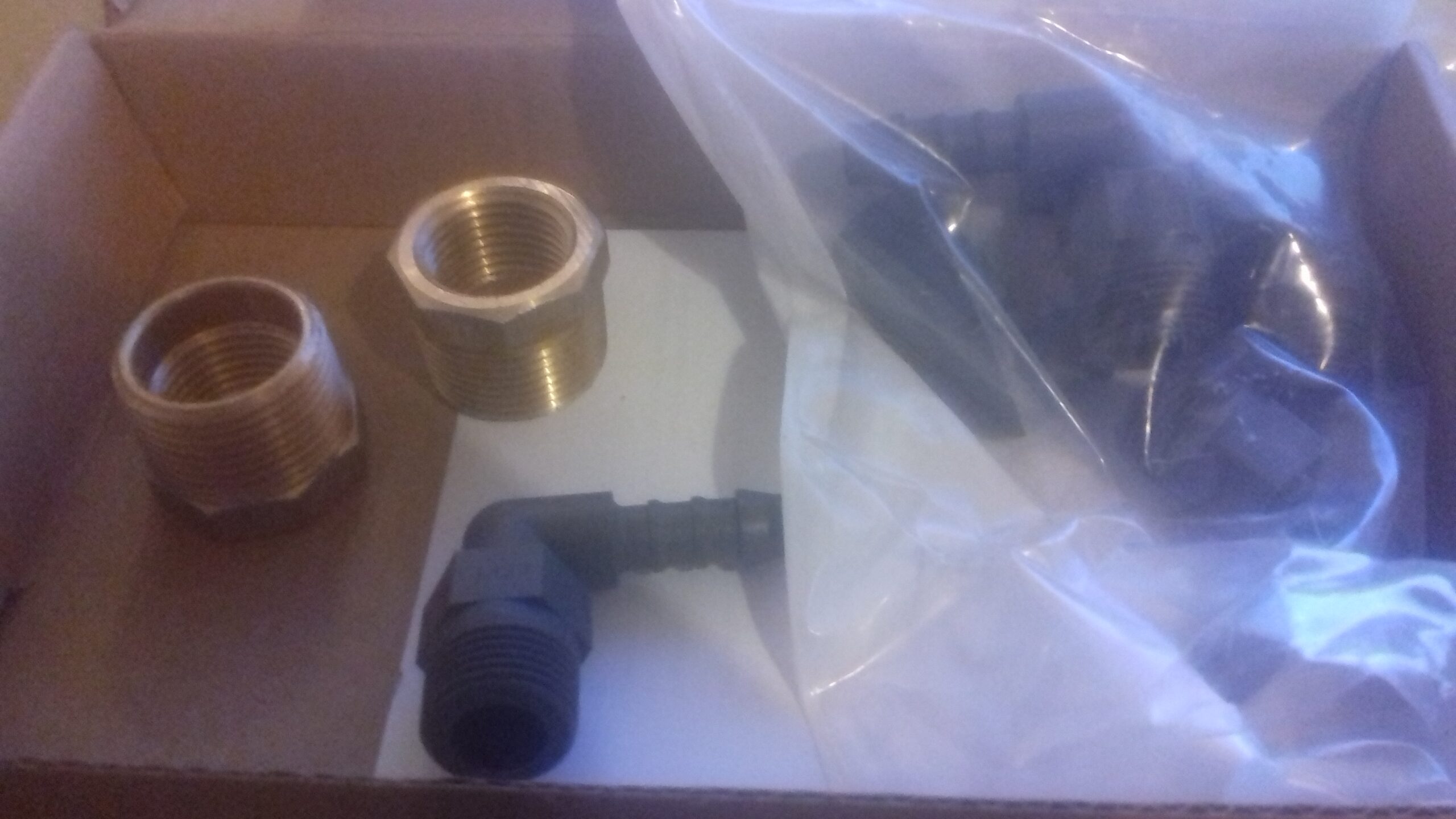 have been some movement in the right direction. Wont take long to fit the whole lot into the boat though so not really lost any time.
All in all the UPS experience was an interesting one but not something that would encourage me to use them. Originally the notification said that the parcel would be arriving at home last Friday so I requested a change to delivering it to a UPS delivery point. That seemed to trigger a return to the depot because the actual delivery was to the house today. Even disregarding the failure to redirect as requested, the driver managed to make a mess of the drop off. Obviously needed a signature from someone so delivered it somewhere across the road and got “Barb” to sign. Then the notification card was put through the letterbox next door. I gave them 6/10 on the feedback because the parcel had arrived but then described the fiasco from my perspective.
Saturday 16/3/19 Mostly working on Matt’s house today but packed in at about 3:00 so I was free to head for the boat! Very windy and a little drizzly so I was working with the cabin hatch shut.
I managed to install all of the cooling water plumbing parts but didn’t have enough of the stainless steel jubilee clips at the moment to do the whole thing with double clips at each hose joint. That is a precaution so that failure of a clip cannot flood (or even sink) the boat due to a hose coming off. It is also usual to keep the seacock turned off whenever the engine is not running which is why I am using the new one rather than the original further aft which would be rather harder to reach if the engine is needed in a hurry.
The system starts with the skin fitting and a hose to the water pump inlet That was where I needed the brass adapter to convert the thread  on the only hose tail I could get to fit the outlet of the ball valve. The outlet then goes up to the T joint and syphon stop valve which will
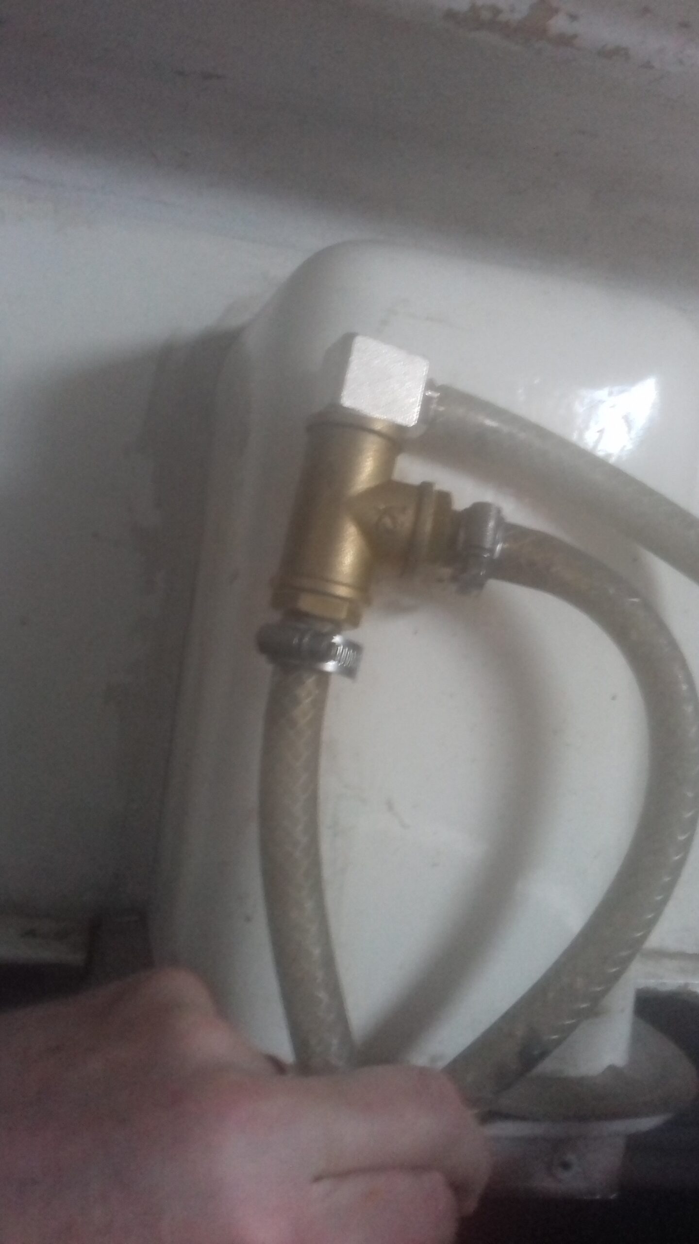
eventually be fixed in place inside the engine compartment air intake. I have more of the right size clips at home and will fit them later. I am not absolutely sure if they are stainless or not as they may be ones we bought for the camper but it is less important when they are well above the waterline and relatively protected from rain, spray or bilge water. The top piece of hose will point out into the cockpit to act as the air  inlet to break any siphon action. That pipe shouldn’t leak water but they sometimes do and if it does it will be a useful tell-tale that water is reaching the engine.
The output then goes back down to an inlet fitting on the exhaust system. Need to add a few P clips to attach the pipes and valve to the duct and avoid the hoses moving around too much, weakening and possibly splitting.
Spent the next few weeks working on bigger pipes as we put in the new drain arrangements for Matt’s kitchen and downstairs toilet. Also achieved a lot with the cabin.
Saturday 6/7/19 Off to storage where I spent most of the morning sorting out the rest of the TCK shelves. Not a particularly nice day to start off with due to 15 degree temperature and low cloud. Occasional quite heavy rain showers rather got in the way of sawing the longer bits of wood.
Followed that by making and fitting the bracket to attach the gear  selection cable on the engine. Managed to do that outside without getting wet because the weather is becoming better and it is warming up a bit now that there is less cloud.
As almost all of the engine bay work is done, I trial fitted the front and 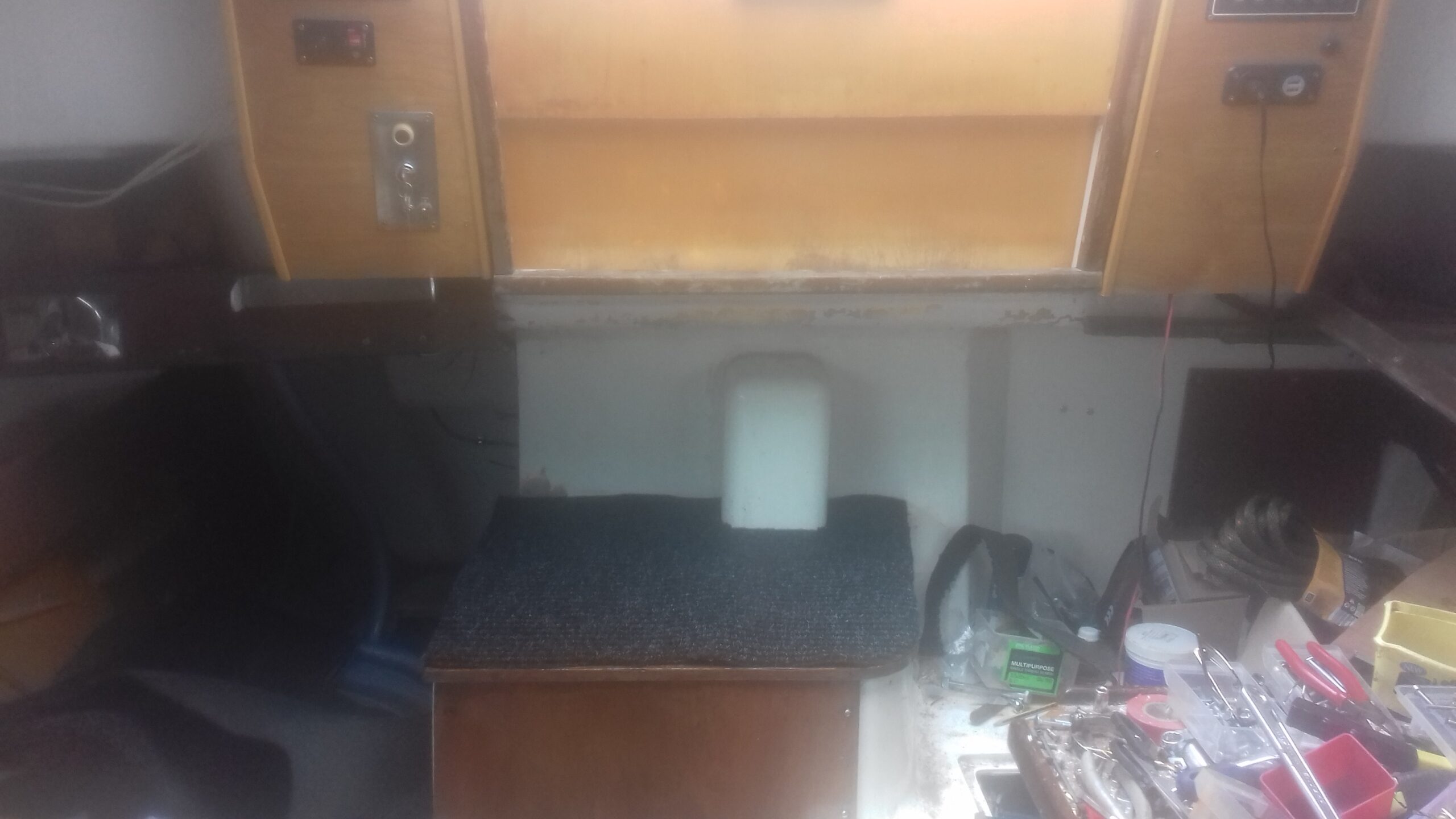 top covers and was even optimistic enough to cut a piece of carpet for the top. It is only a bit from the offcut of the house entrance hall carpet but signifies a need to protect varnished surfaces while the rest of the work proceeds.
Not sure what screws I will eventually use for the front panel but might be brass or stainless from an appearance perspective as corrosion resistance should be a relatively minor issue.
Saturday 31/8/19 I got time to create the grease gun holder out of the original bracket and a couple of bits of old number plate.
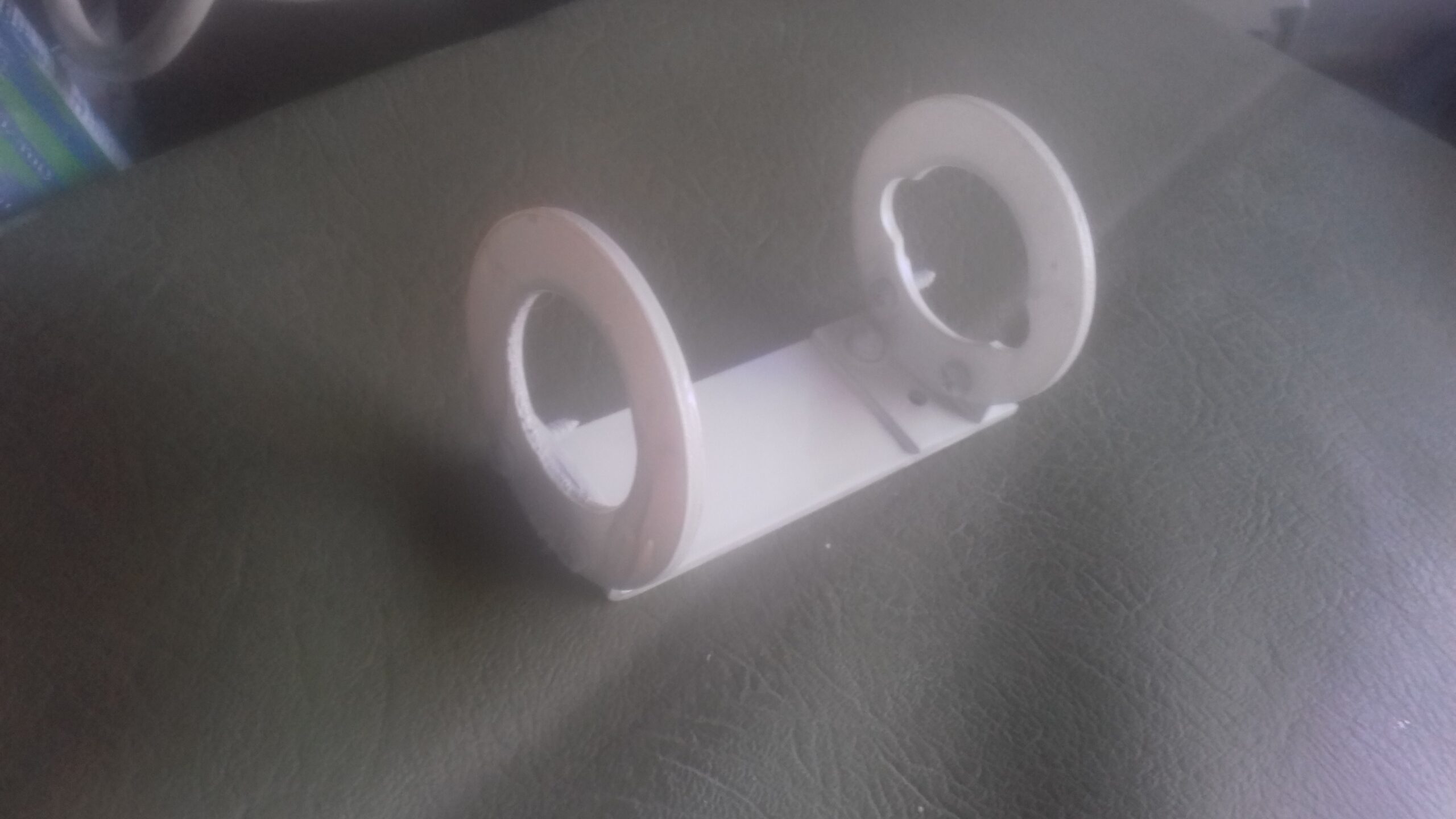
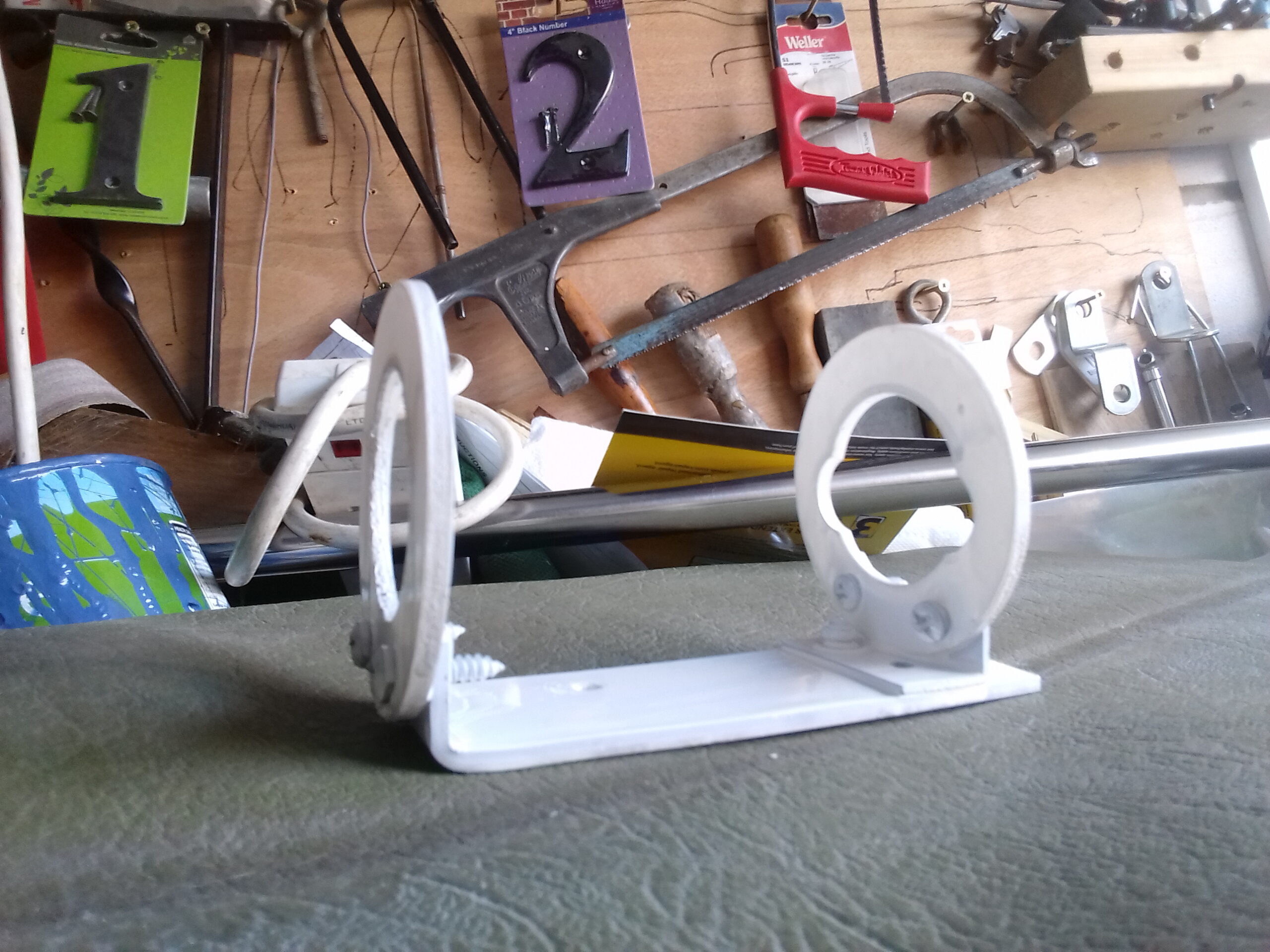

The grease gun is connected to the space between the two seals and replaces a screw down type of grease injector. You are supposed to give the seal a bit more grease each time the engine is run and that maintains the lubrication and waterproofing of the seals.