I have already written about the engine related electrical system install and included the charging of the starting and domestic power batteries from the Dynastart. Apart from the starter and fuel cutoff solenoid valve there has been no mention of other electrical loads and the two battery isolation switches are the nearest any of those circuit diagrams has come to dealing with electrical devices.
When Rathenice was originally launched there was limited lighting equipment available for caravans, boats and camper vans and mostly that was based on filament bulbs or the relatively new fangled transistorised miniature fluorescent lights. She arrived with two  fluorescent lights fitted on the bulkhead in the main cabin, a single lamp in the heads compartment and two filament lamps in the fore cabin (These basically looked like white versions of classic mini or morris minor indicators and used the same bulbs). Obviously those have a relatively high electrical demand for the low capacity battery originally fitted. Probably around 5 amps if they were all on at the same time.
Navigation lights would have been similarly demanding on electrical systems. probably adding a further 5 amps demand making total battery life something less than 10 hours if all the lights were on at the same time.
As we start the restoration work we have at least twice the storage capacity available and can plan to use the far more electrically efficient LED interior lighting and navigation lights that are now available. These should also be much more reliable than the original fittings because the lifetime of the light sources is a hundred or so times the original, there are no spring mounted bulbs to corrode and give poor contact and no slide switches as were fitted to the filament lamps.
My general principle for the electrical system has been to designate some of the equipment as essential and have that switchable between the two different battery systems while the non-essential circuits all run from the gell batteries as the domestic system. Almost all of the equipment is able to be turned off via the two isolator switches but bilge pumps and engine starting both get their supplies direct from the battery side of the isolator switches. That makes for a slightly complicated fuse arrangement whereby there are four high capacity fuses mounted in the electrical locker on top of the isolator switch cover. There are fuses for “before” and “after” the isolator for each battery and these are the rather clever car type fuses that have an led built in – If the led is glowing when something is turned on then the fuse has blown so that should make it reasonably easy to fault find if I ever get a problem. I carry spares of the same type but the standard fuses also fit the holders.
Some of the earlier photos have already shown that there are switch panels either side of the companionway.
- The port one handles the bilge pumping system as a safety critical essential item that stays live regardless of isolators. The battery
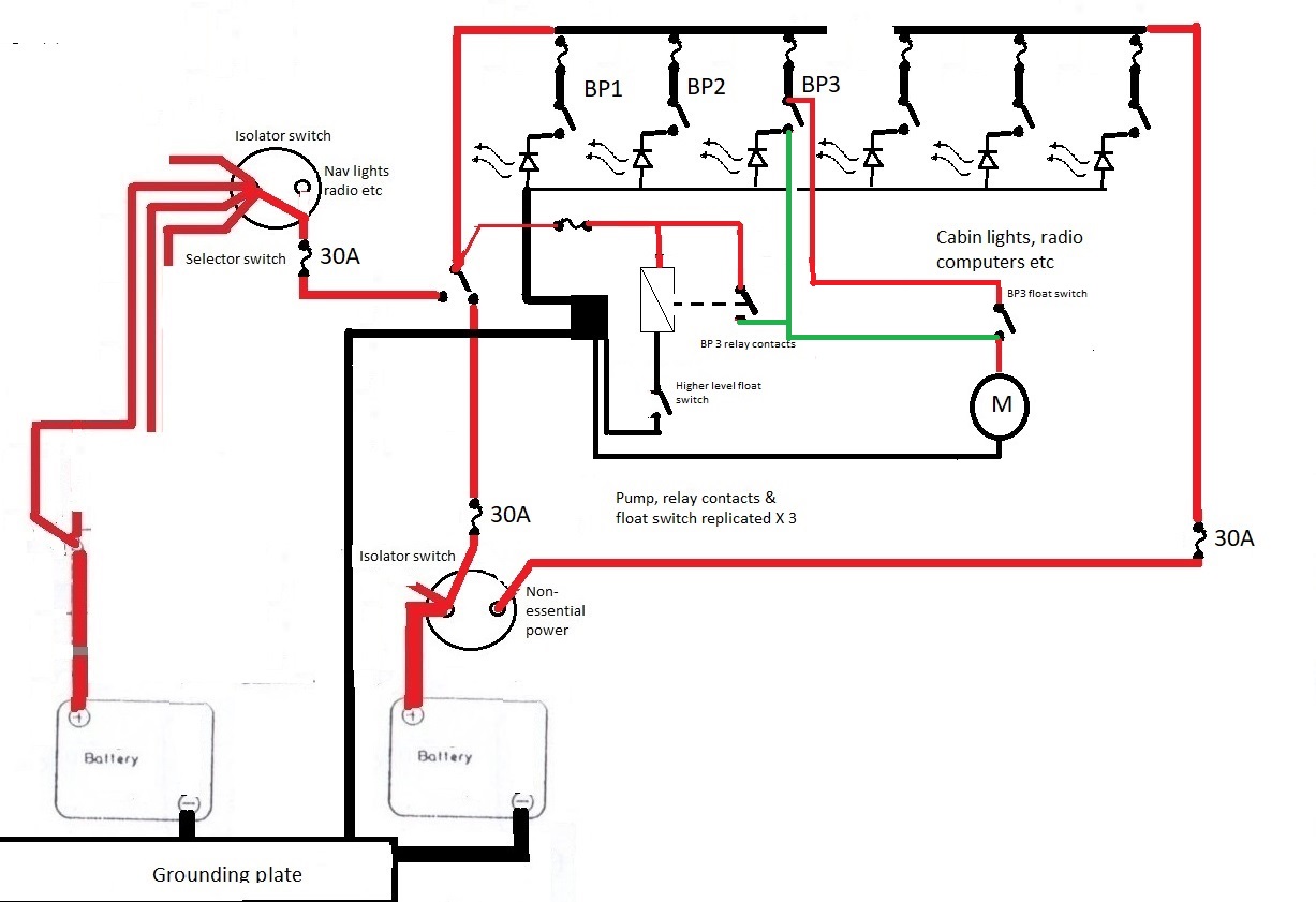 that drives these is selected by a toggle switch so either of the batteries going flat does not interfere with the safety critical systems. The three main bilge pumps each have their own fuse and switch which will run the pump irrespective of the float switch.
 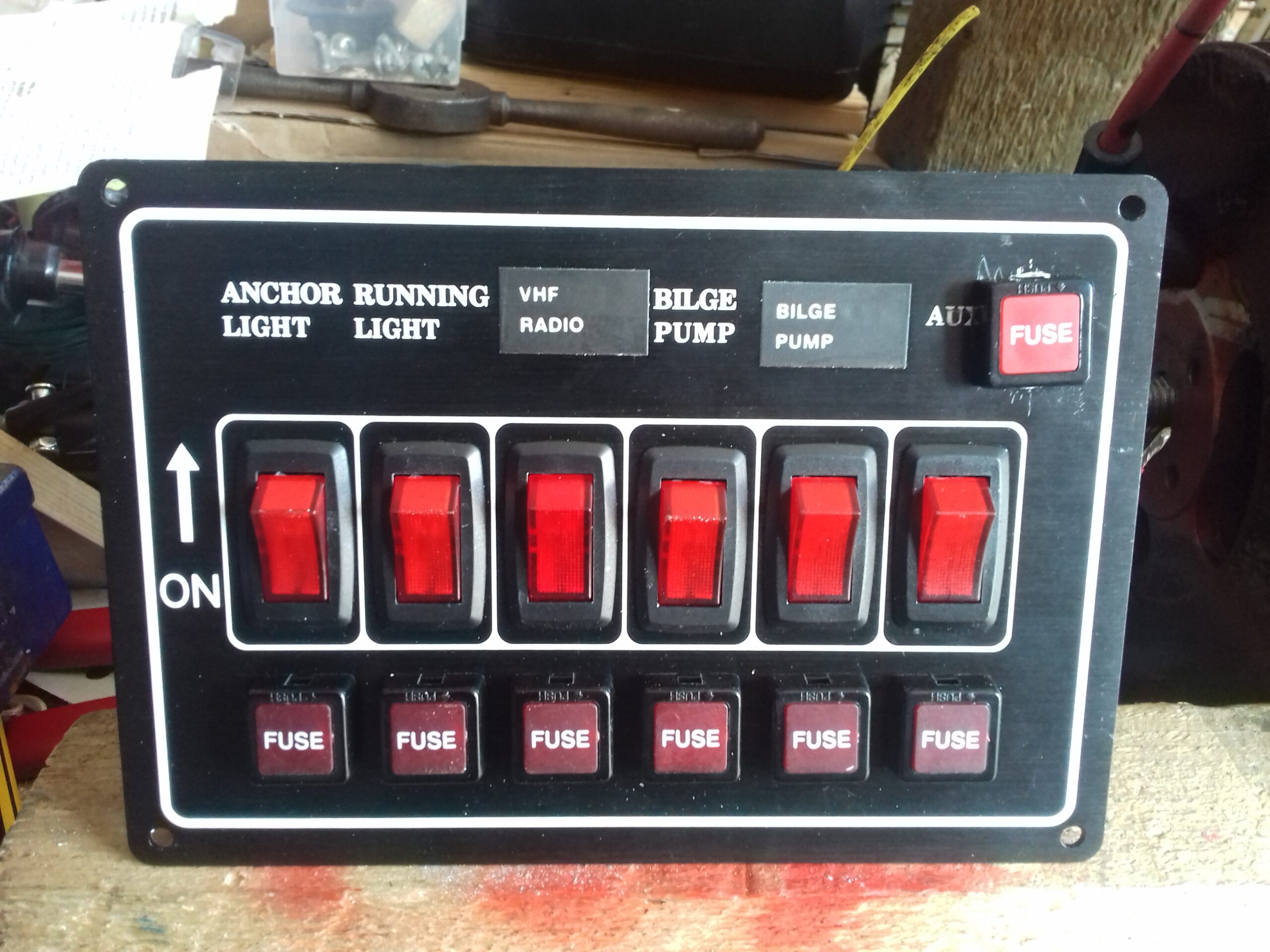 The switch lights up if it is on or if the float switch triggers the pump. The extra fuse above and to the right protects a fourth float switch and relay which will turn on all three pumps in the event
 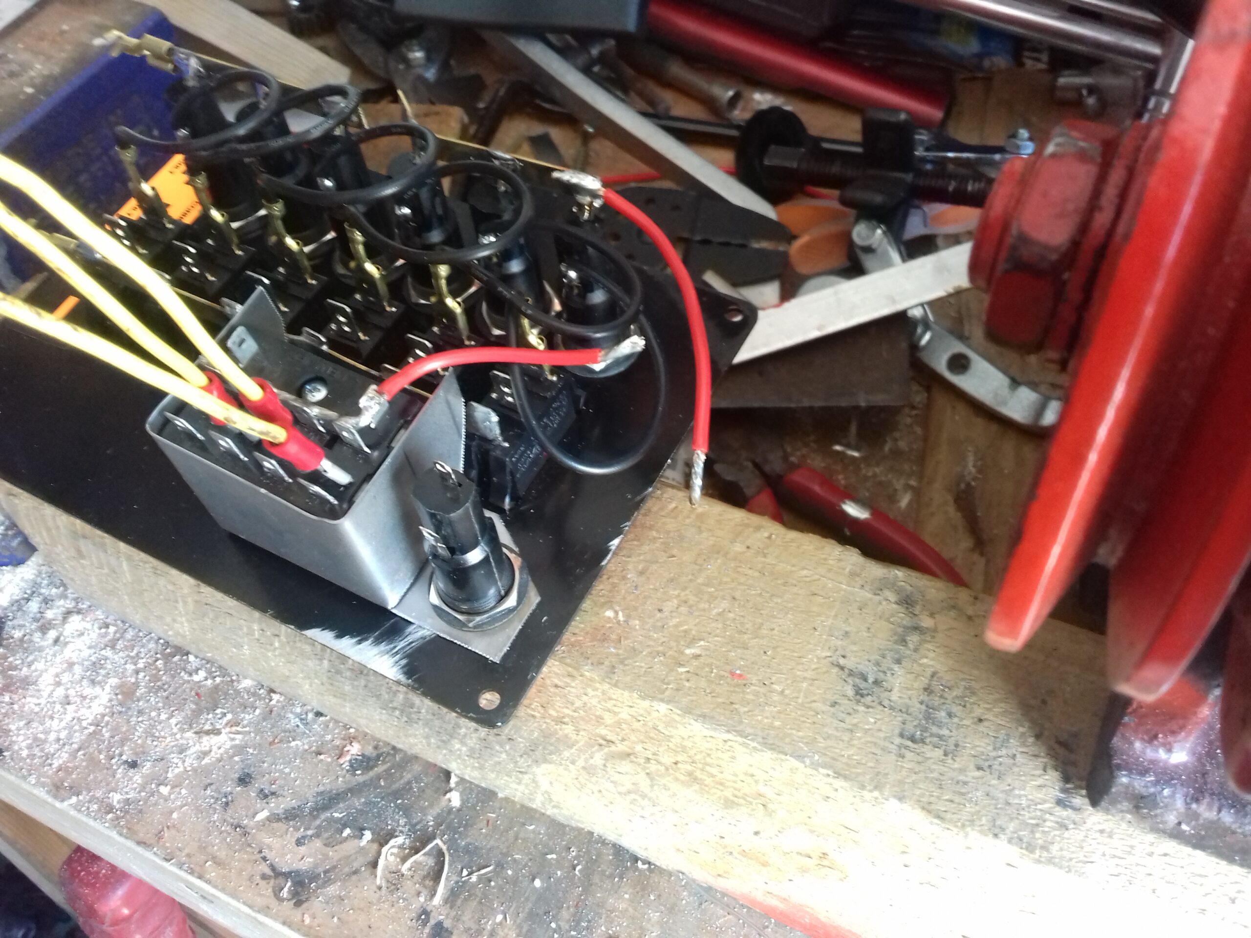 of the water level in the engine compartment going above the level that over tops the bulkhead between compartments.
- The rest of the port panel operates the “car” type radio, VHF radio, USB outlets etc running off the domestic batteries after the isolator switch.
- The starboard switch panel deals with navigation lights plus the echo
 sounder and internal lighting. These can all be selected to operate from the domestic or starter batteries and are connected after the isolator switches.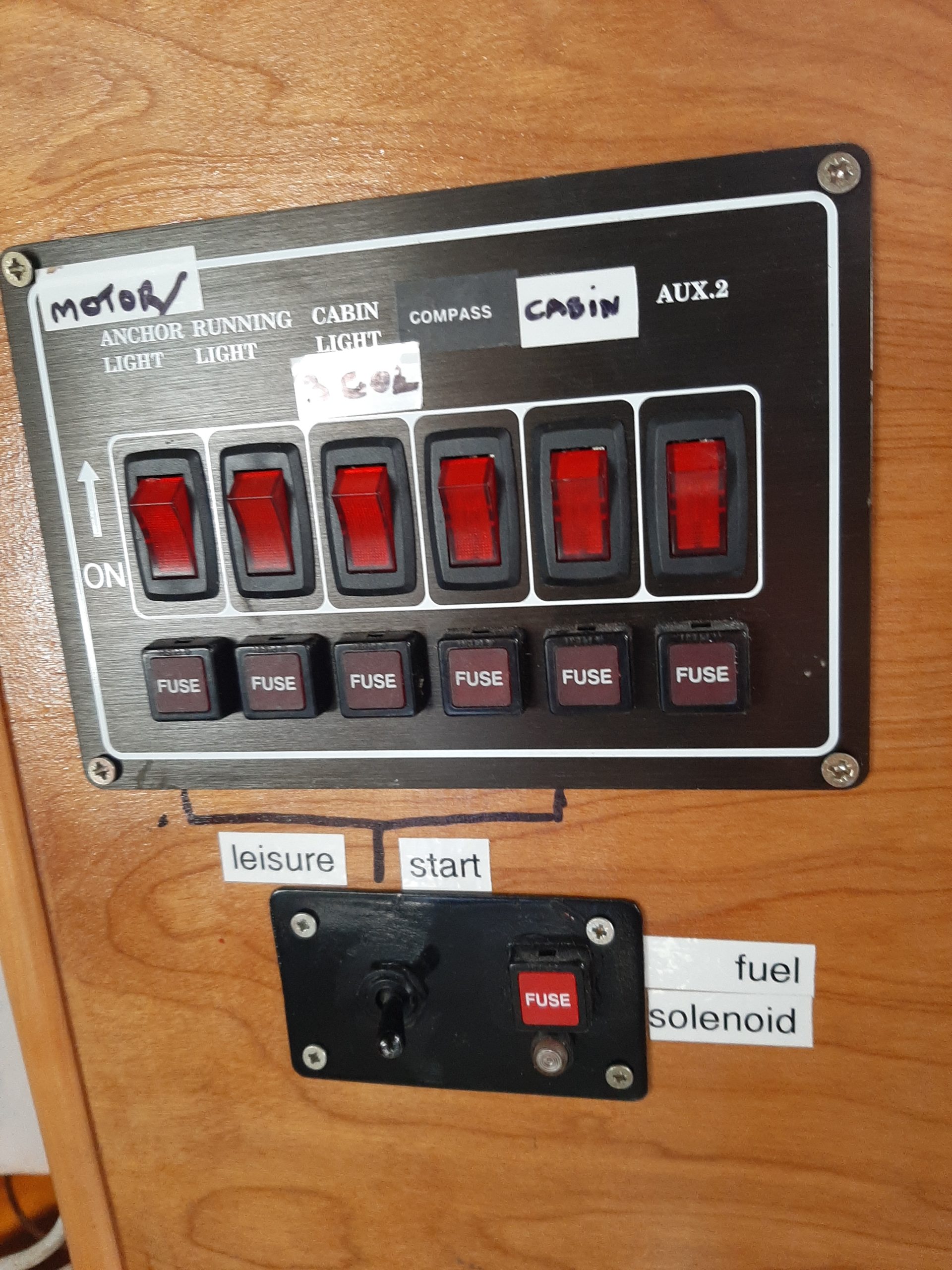
All of the circuit switches have a fuse and a built in LED to indicate whether or not the circuit is receiving power. Again that will help with fault finding as a blown fuse will prevent the switch lighting up.
Cabin lighting still uses a lot of the original 2 core cable that was fibreglassed onto the cabin roof structure. This is relatively modern cable using the blue & brown colour convention (Brown for +ve). All additions made by me use twin red & black cable (Red for +ve as per battery cables) or similar multi core cables where appropriate (eg mast connections – 4 core and bilge pumps – 3 core). Where possible these either run through plastic conduit fibreglassed onto the structure or are bundled together with cable ties and attached using plastic P clips or cable tie bases. Connections to switches and other suitable items are almost all made using insulated crimp on car type connecters (mainly 1/4″ blade type) or by soldered joints protected using heat shrink tubing. I have also often tried to improve reliability by soldering the conductors inside crimp on connecters where this can be done easily.
My plans for the domestic lighting basically replace the original fluorescent cabin lights with one or more LED equivalent lamps supplemented by LED spotlights in appropriate places. As these draw a fraction of an amp each we can have a lot more lamps in places where light is needed (eg inside the engine compartment, reading lamps near berths, map lights for navigation at night etc) without coming anywhere close to the same drain on the batteries while also avoiding the risk of sparks from switching high currents near gas or petrol.
Generally there’s nothing exciting about fitting lights or stringing wires so the practical diary part of this post is mainly limited to actually making the light fittings from individual parts rather than screwing them to the boat in particular places.
Saturday Installed the proper bilge pump wiring so the one in the engine bay now works off the “always on” switching in the port side control box. Doesn’t have the float switch controlling it yet because I left the mounting plate behind last time. No more water in the bilge than when I was there last so not enough for the pump to actually dump it overboard but there is enough to show the pump works and confirm that I will need a one way valve in the pipe as the water flows back to give over an inch sloshing around near the electrics and engine.
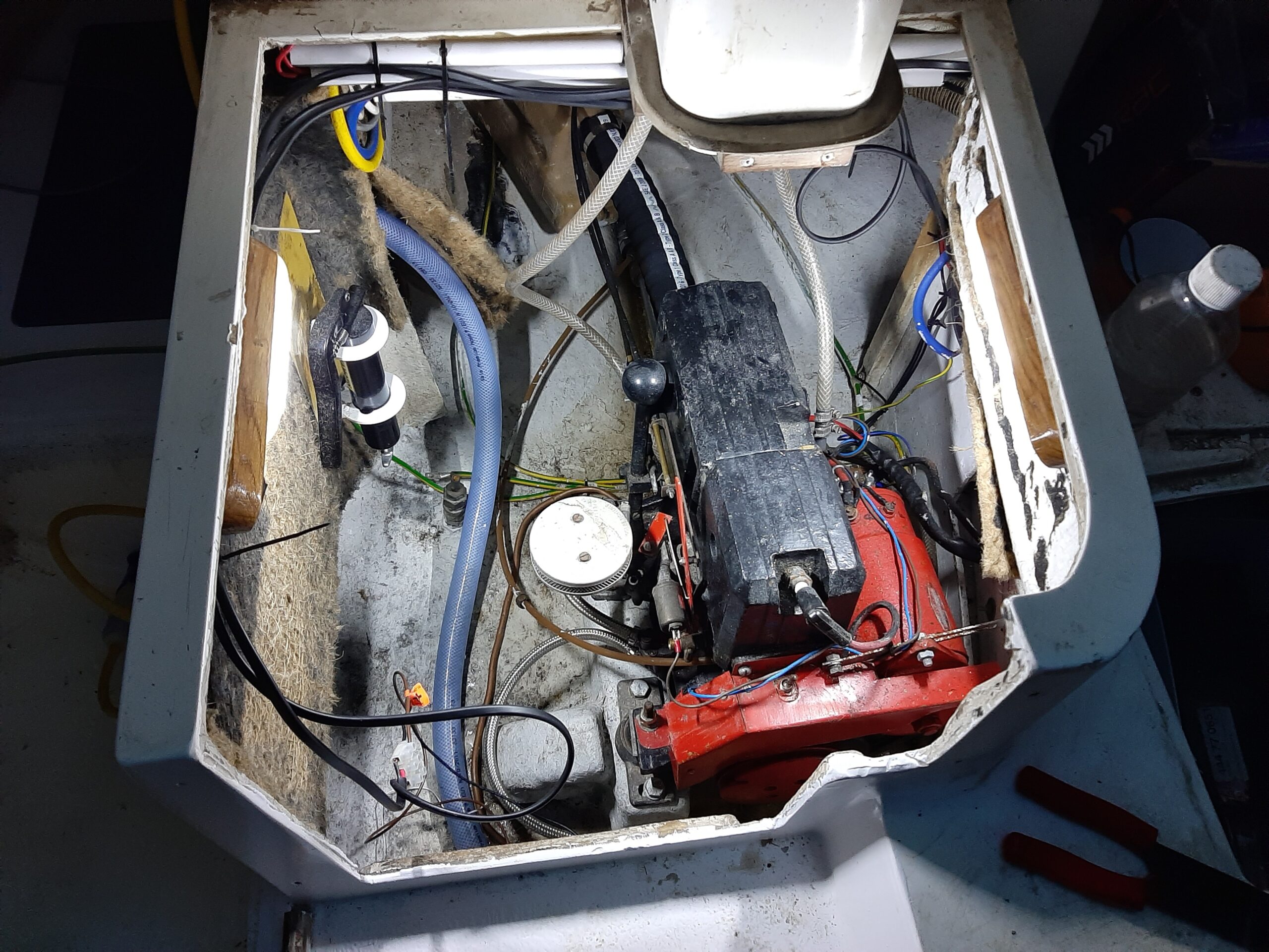
The same wiring session has now got me a light in the engine compartment which will also run off the “always on” supply. Seems to make sense to me as any light needed to help get the engine running seems to me to be a valid emergency supply. That means it needs to be available from either battery system like the bilge pumps.
Added the first of the spotlights into the front cabin although, like the heads, that will need re-fitting once I have made the spacers that make room for connectors between the bulkhead and the spotlight base.
By 5:30 I had made what will become four spacers by cutting out blanks with a large hole saw then opening out a smaller cavity in both sides of that to house the connecters and chiselling out the waste. 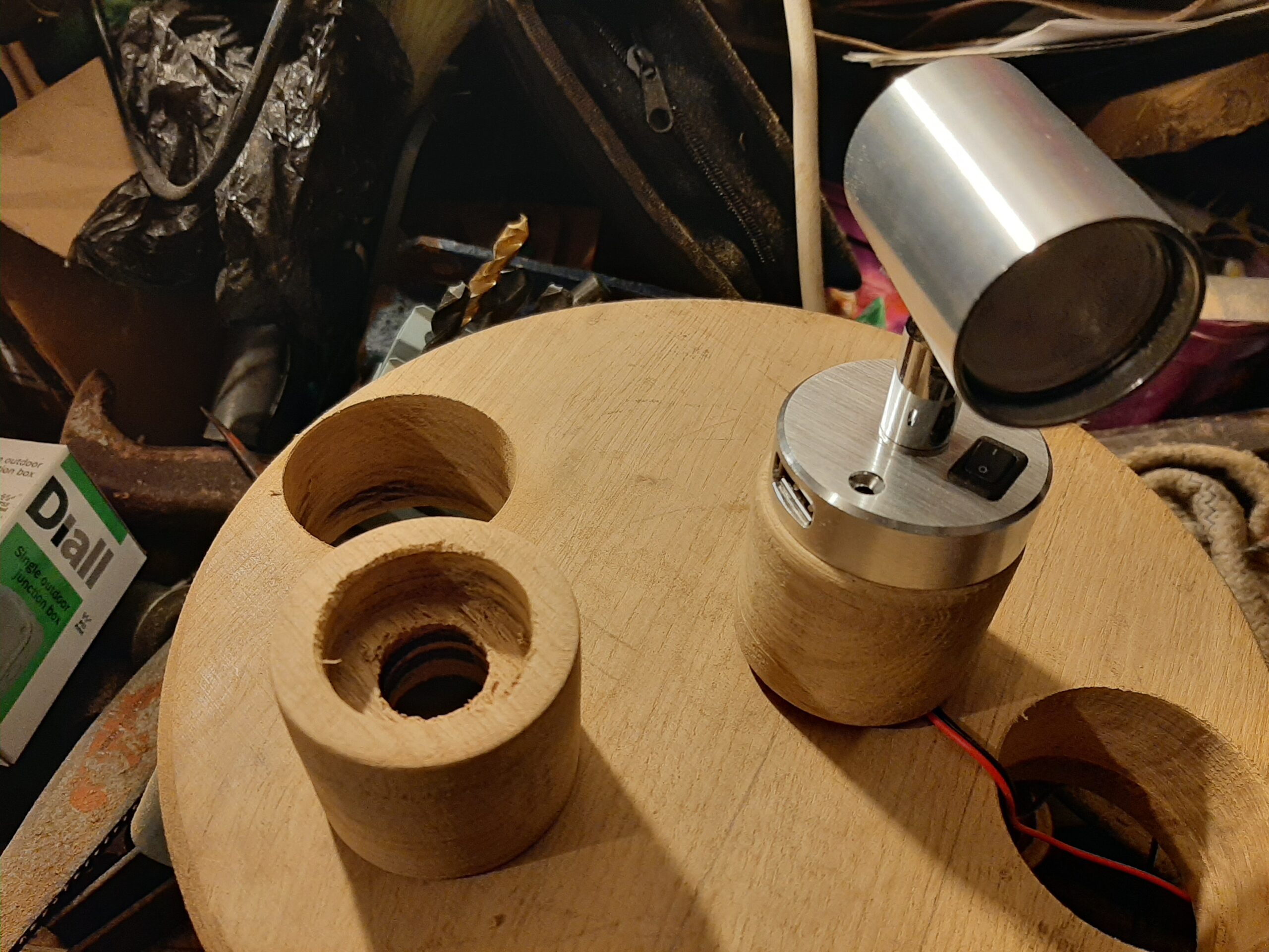 Finally added a third hole-saw bore to get the cables in and out. Once these have been sawn in half thickness wise and varnished they will do the job and only need a little more carving for the ones where the cable comes in along the bulkhead (ie two in the forward cabin and the one in the heads). Those and the semi rectangular blocks for the cabin and engine bay lights are coming from a nice piece of oak that I got from B&Q. The lighter colour should provide a nice contrast to the colour of all of the existing woodwork and might even match the colour of the plywood used for the electrical panels. Hopefully the remaining pieces of oak will be suitable for making the packing pieces around the flag pole mounting on the transom otherwise I will have to get another piece.
Wednesday Set up the bandsaw and then used it to cut the spotlight spacers in half and also cut out the blanks to make the switch and lamp 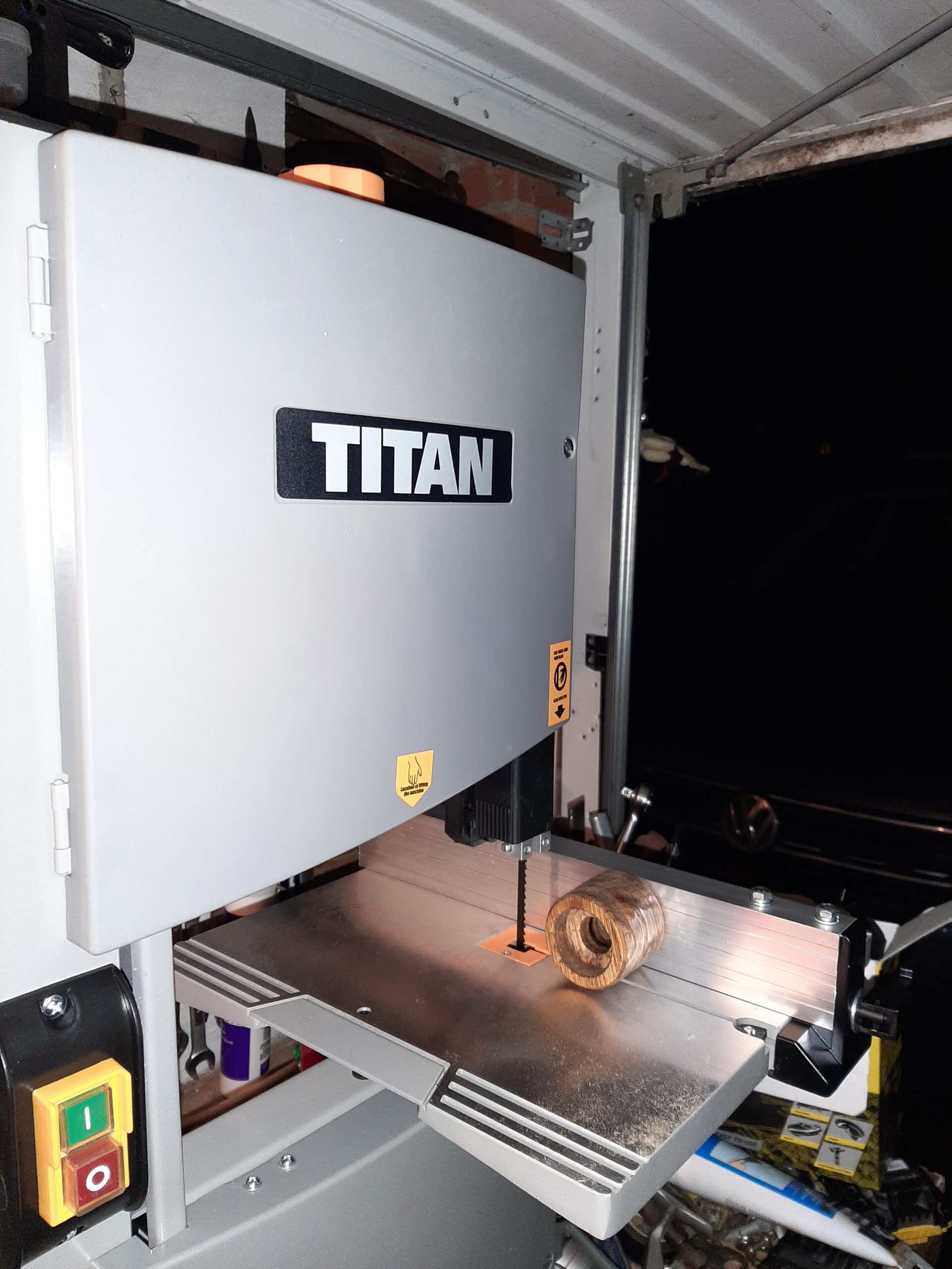
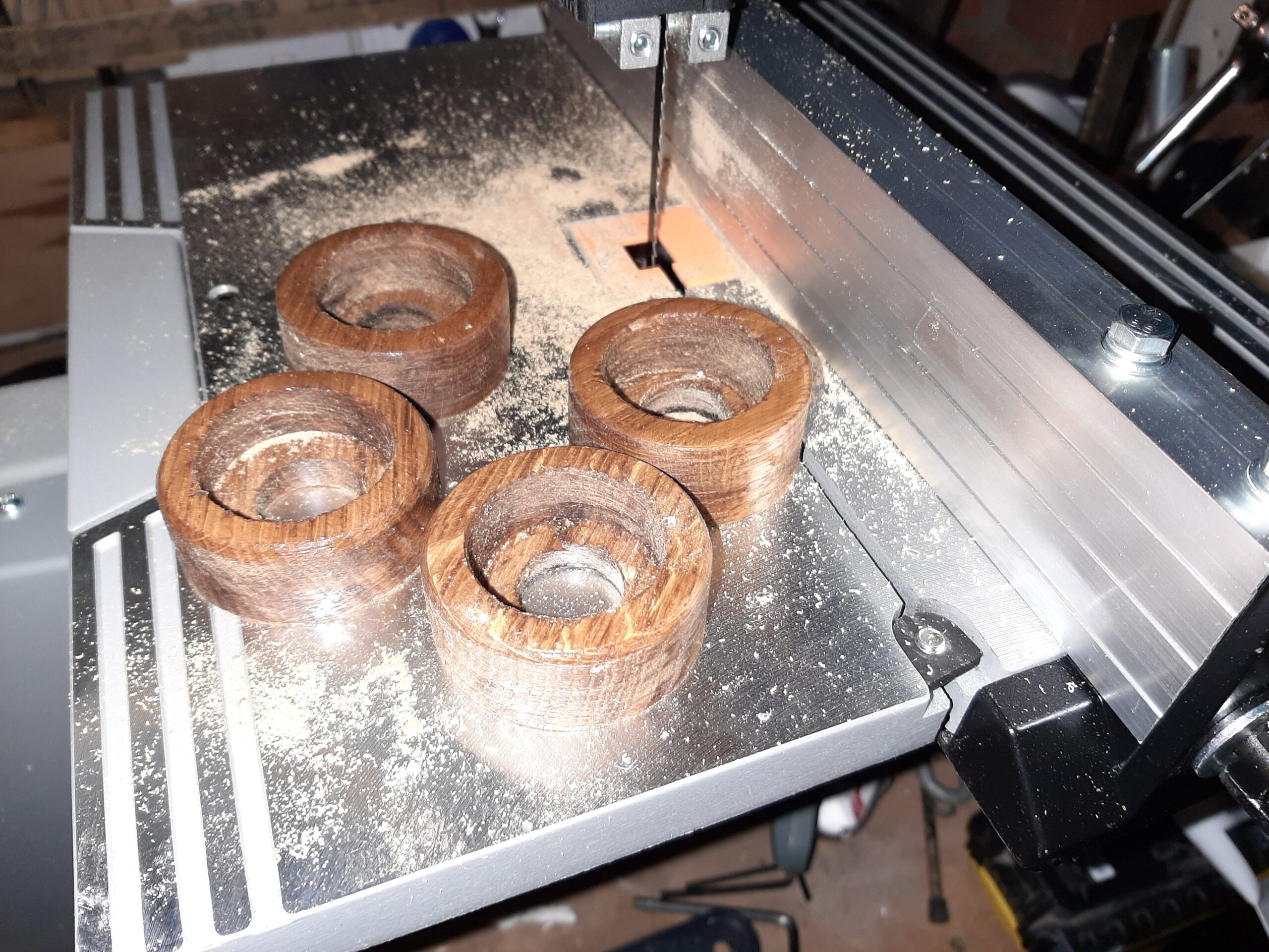 spacers for the engine bay and galley. Definitely a very effective piece of kit and did a neat job on the oak even with what I thought of as a very coarse 6 TPI blade. Seems it must have been damaged packaging that got me the price reduction as the parts were all there in knotted bags and no sign any of the parts had been previously installed.
It leaves the slight wavy surface that I expect from a band saw on the longer cuts so you can just see it on the photos. However that is not noticeable on the round pieces even when looking directly at the parts. There is a lot more shaping still to do on the rectangular pieces and they will need a little sanding to smooth all the saw marks out before varnishing.
I think this tool is going to transform the standard of our detailed woodworking much the same as the chop saw did for the building work on Matthew’s house.
Sunday Church as usual followed by our carols by candlelight service.
I managed to sneak in an hour or so of boat building by doing a little more shaping of the light mounting spacers. Sawed the taper into the sides and shaped curved ends on them. All marked out to drill the 20 mm holes for the switches.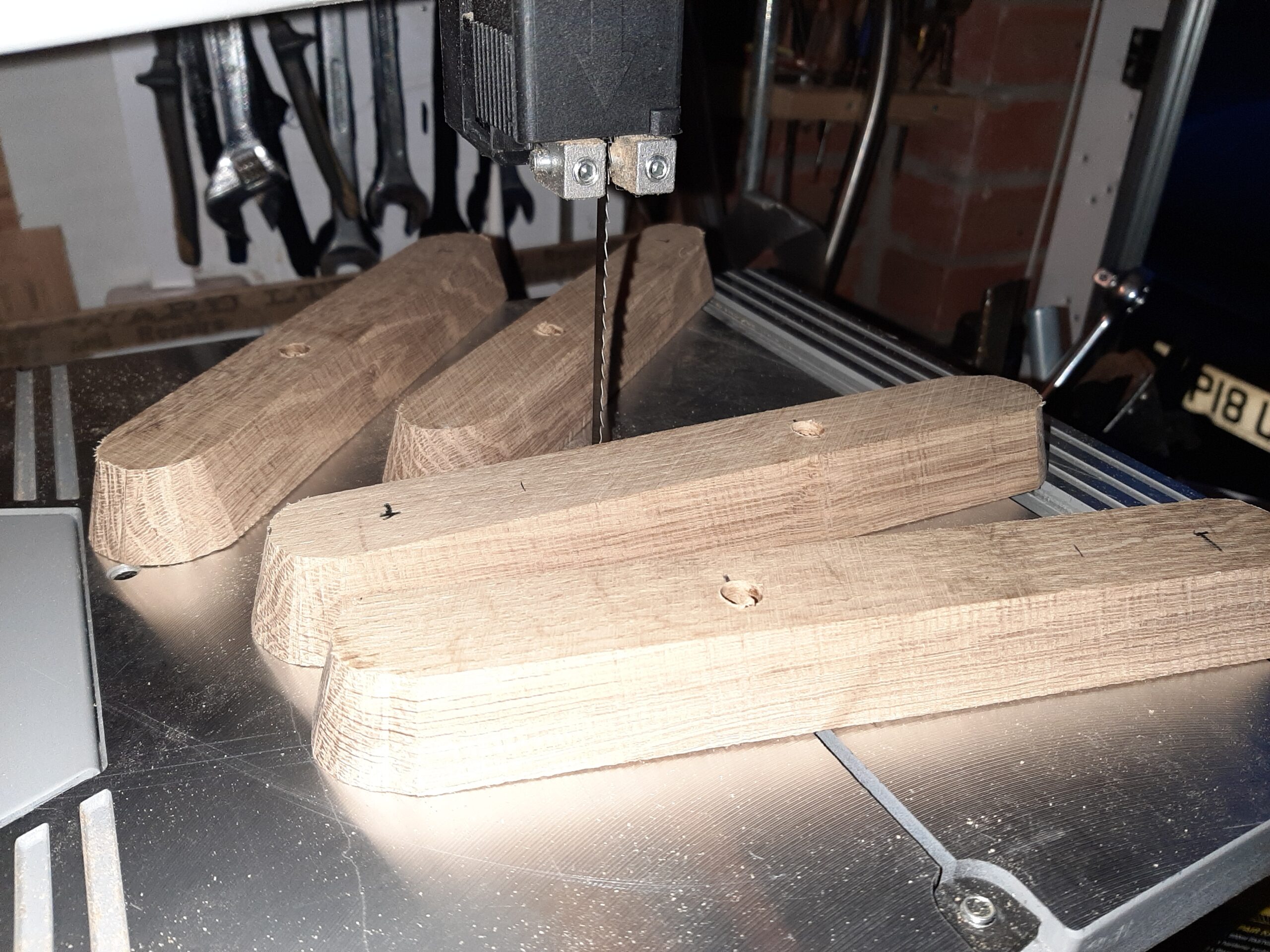
To get decent accuracy I think these will need to be done with the step drill bit. Before I can make any more progress I need to work our whether it is somewhere in the garage or “lost” among matt’s workshop clutter. I cannot really criticise as his workbench is no worse than mine but he does have the excuse that the whole shop space is much smaller.
Once the first part of the hole is done I will sand the surfaces smooth with the belt sander before routing out the cavity in the back of each one for the connecter block and then varnishing them.
Thursday 19th Drilled out the 20 mm holes for the switches in three of the spacers and then took out a bigger diameter on the rear to help with access to the wires. The fourth one doesn’t need a switch because it is one of a pair in the engine bay and is controlled from the opposite
one. Next job was to build a jig to help with routing out the connection cavities in the back. General principle is to keep the 1cm cutter 0.5cm off the centre line and with end stops to stop me routing too close to the ends of the blocks. 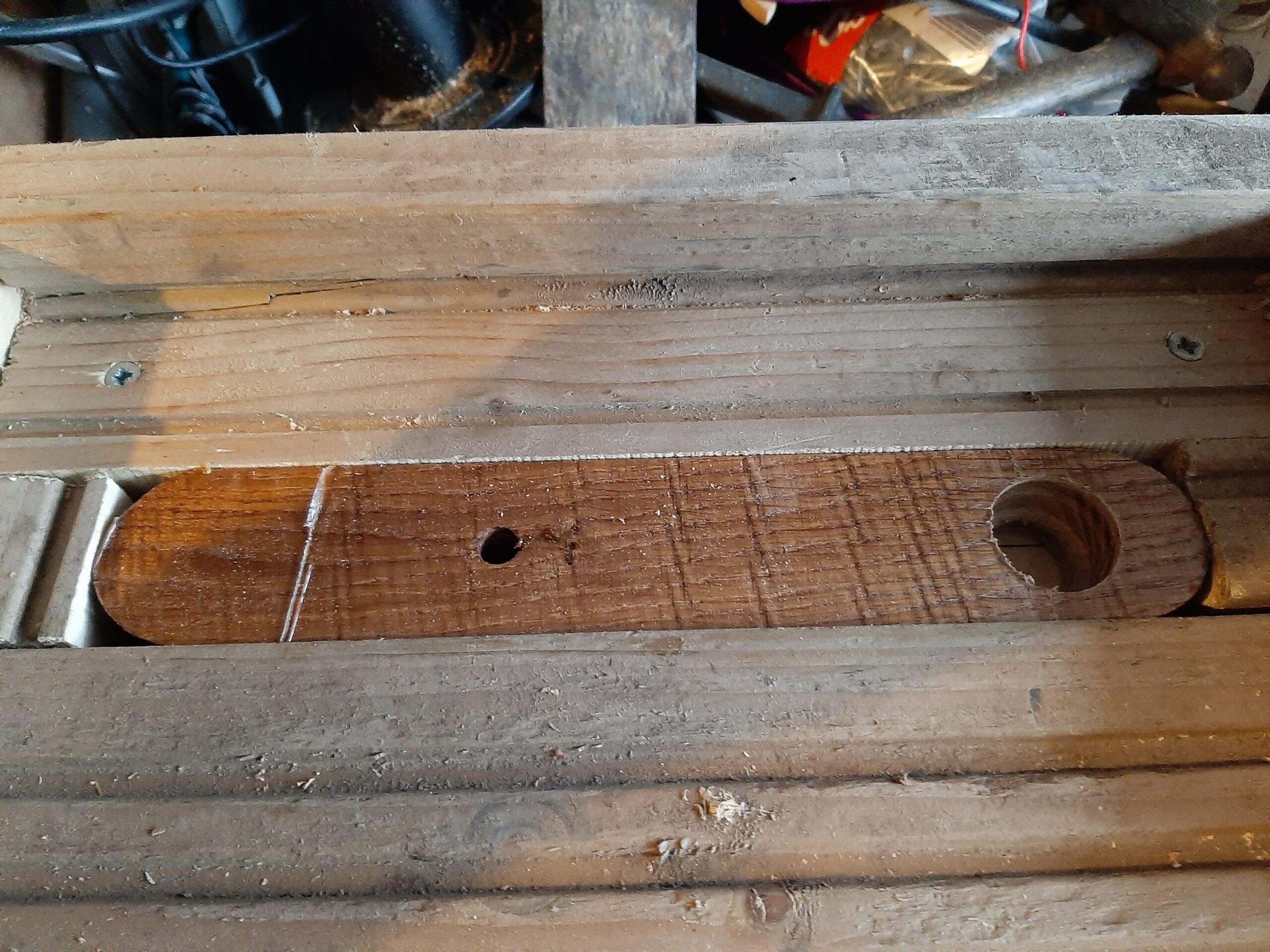 It is a bit crude and I did not achieve a reproducible precision machining job but the resulting pieces are definitely fit for purpose and there are no signs of the cutter bit having got too near to the surface.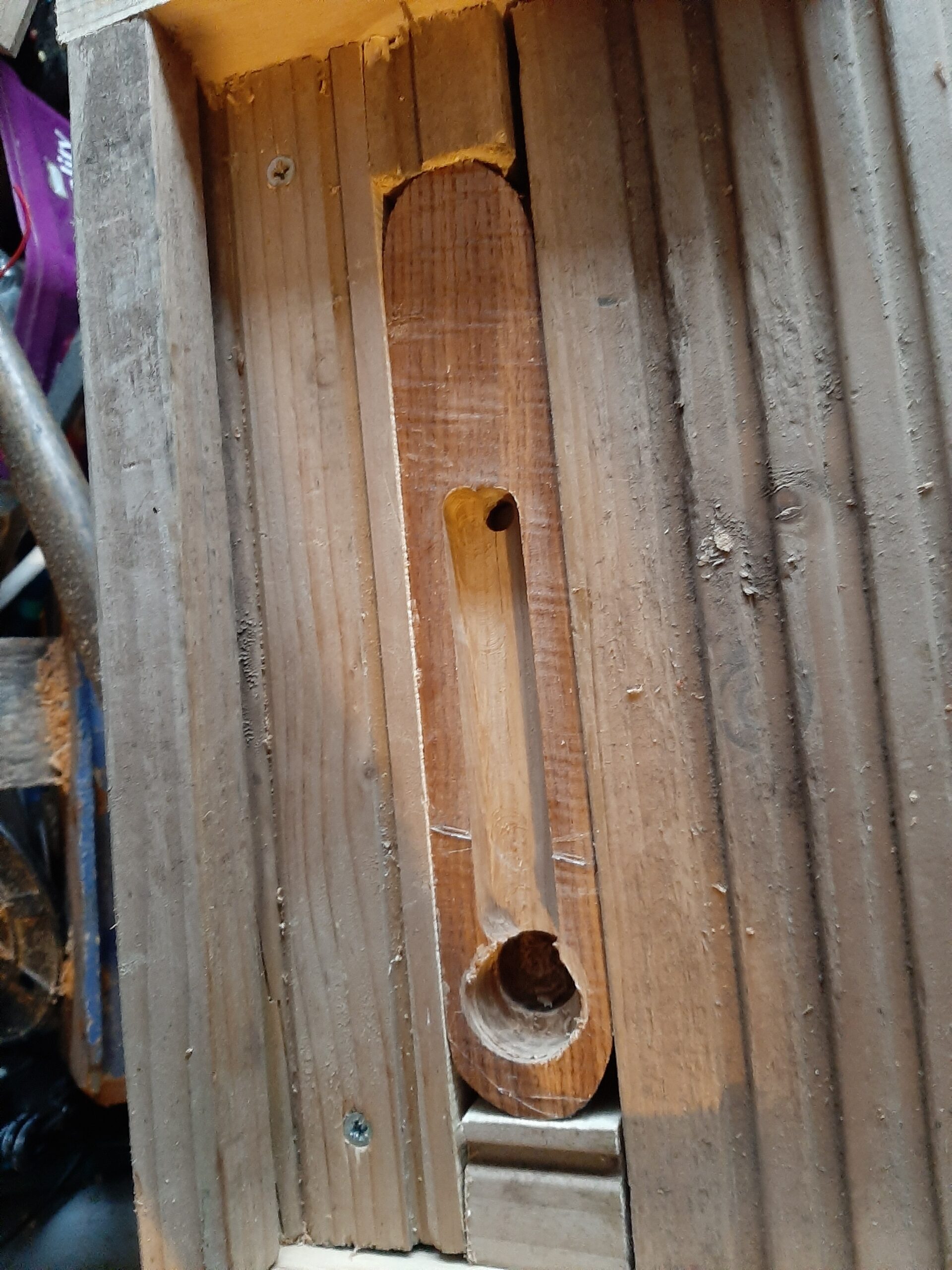
Having done all those bits of woodworking I sanded all the parts and tried to hoover up the router chippings and sanding dust well enough to do another coat of varnish. Hopefully it will turn out OK even though it got much more humid and started to rain hard just after I did the varnishing. I suspect they will need a third coat of varnish anyway so it may be Sunday before I fit them.
Thursday 26th December Awake and having breakfast by 7:30. Installed all the switches and lights onto three of the spacers leaving drilled and countersunk 4mm holes to mount them. Wires soldered and adhesive lined heatshrink is also in place (but not shrunk yet). The other spacer is the non-switched one which is already over at the boat and so doesn’t need anything other than the light screwing to it.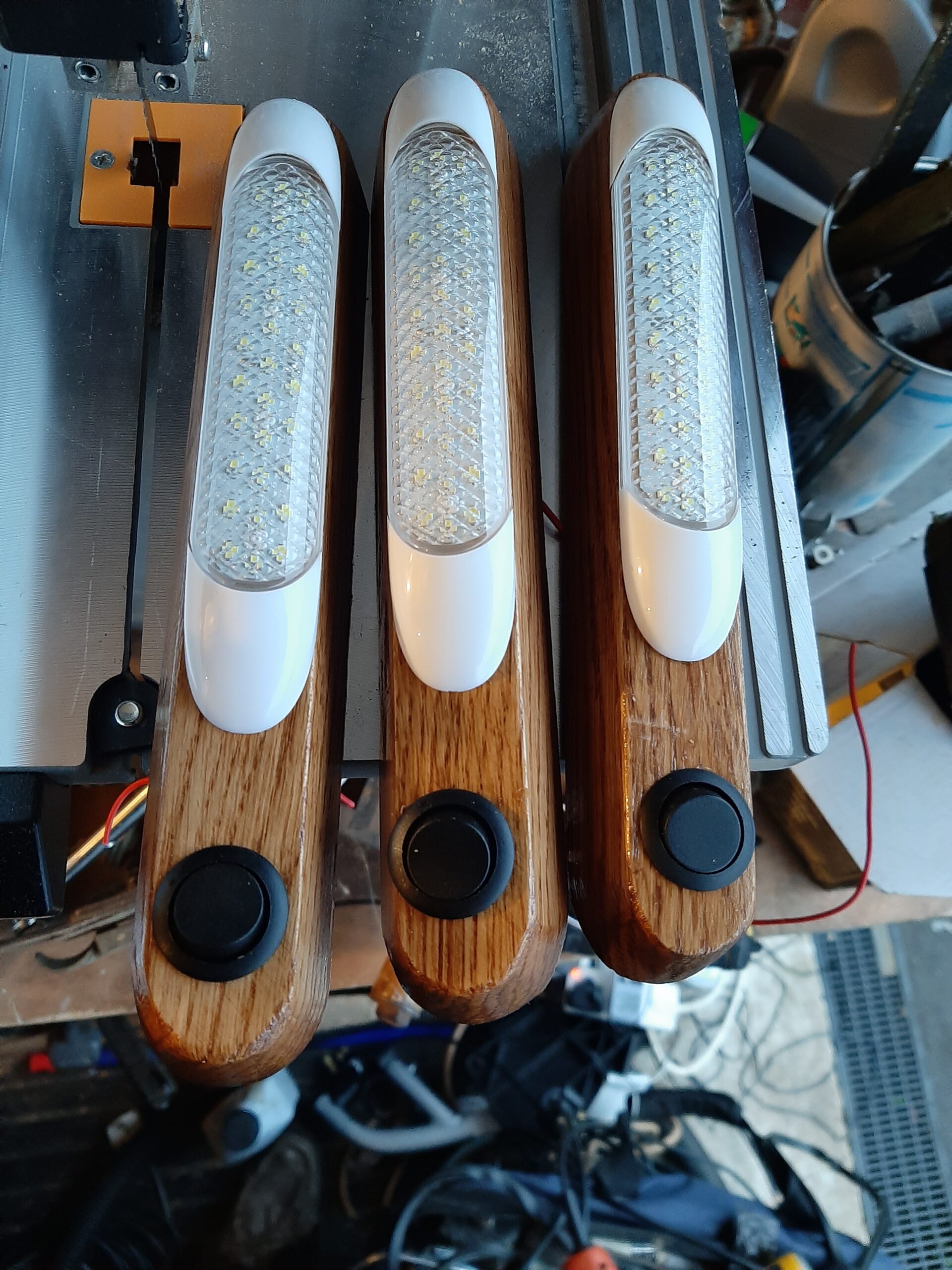
Saturday 28th Dec 2019 During the two hours at the boat I managed to fit the water pump, both lights in the engine compartment and also  the one beside the galley.
 Next job would have been to fit the three round packing pieces under the spotlights in the fore cabin and head but I only had another 20 minutes or so before I needed to be on the way.
Wednesday 1st Jan 2020 Started the day with Annabel’s birthday cake. Home about 1:00.
Woke at 8:00 and went to the boat by a little after 9. 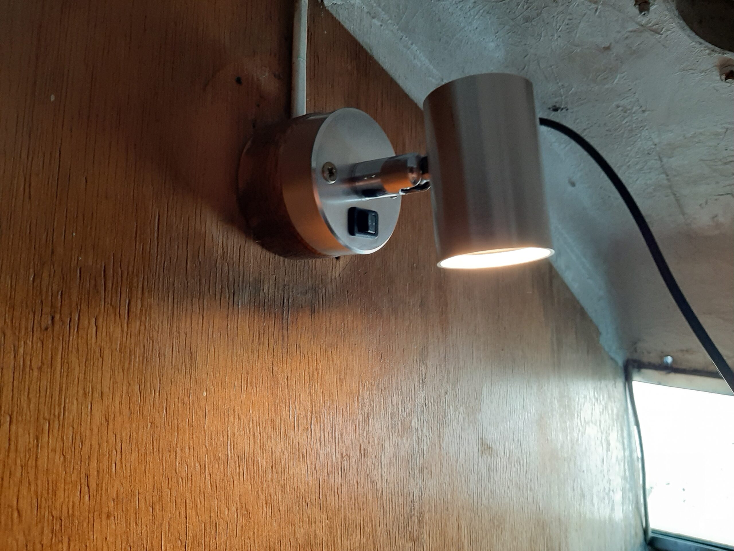 Wired up the three spotlights with the spacers.
So that is the cabin lighting build finished. There is also one other lighting mount which I made out of oak and that one holds another LED which is designed to be mounted on steps so you can see where you are putting your feet. 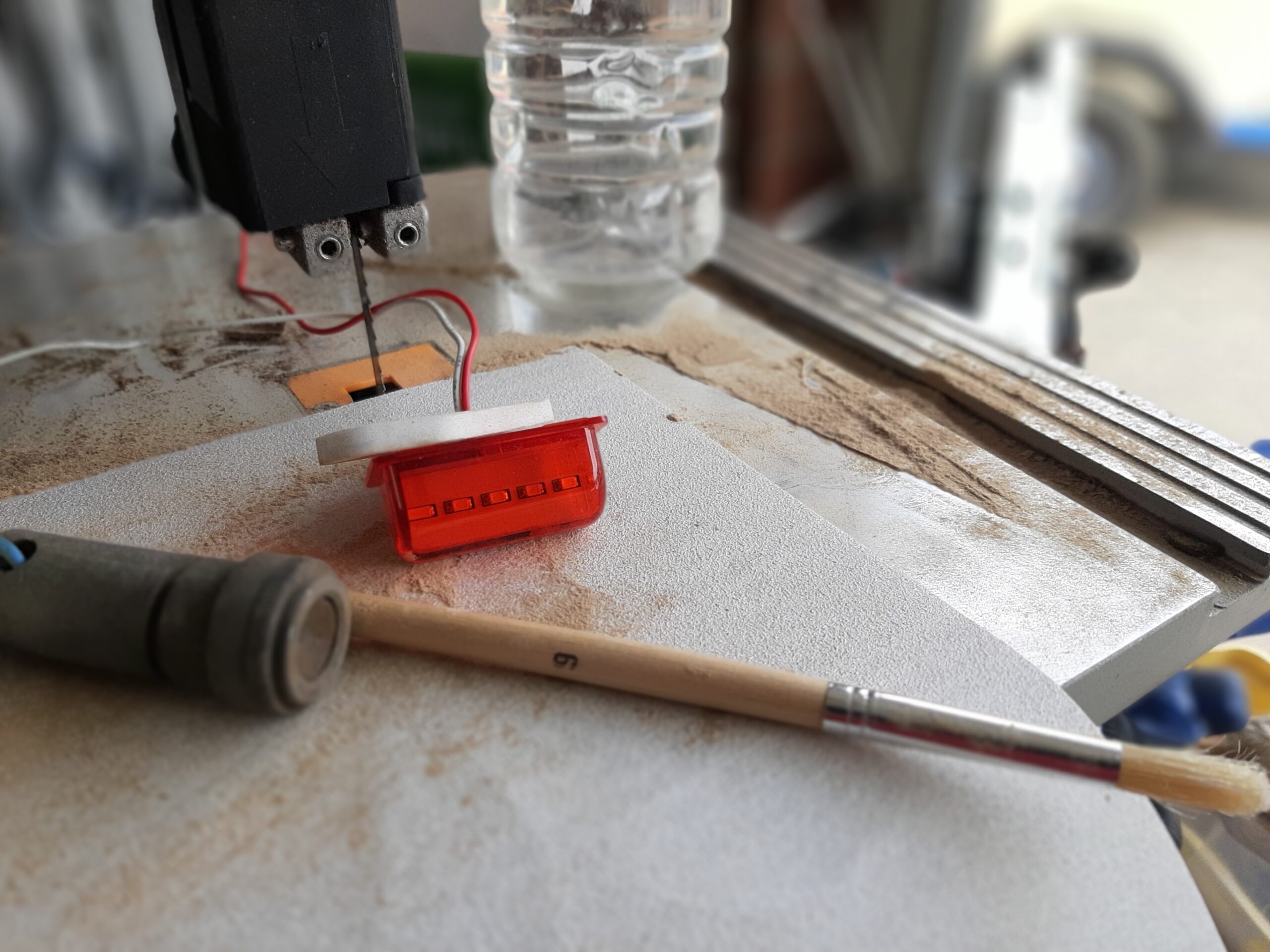 As it is red it seemed to me to be potentially an ideal compass light as I can fit it where it would not be visible to other boats but would illuminate the old compass (All of the original radioactive light sources seem to have lost their isotope driven glow). The original light had a tufnol case with steel torch bulb base and bulb holder so I should be able to create less magnetic deviation than that caused. Obviously I checked the metal case and tested it when lit up to make sure it didnt influence the compass bearing and it is assembled using stainless steel screws (You did know they are non magnetic didnt you?).
Saturday 11th April 2020 Woke at 5:30 and had done all the washing up etc to be out on the boat by 7:30. Next job was to create the oak wedge that will hold the compass light at the required angle. 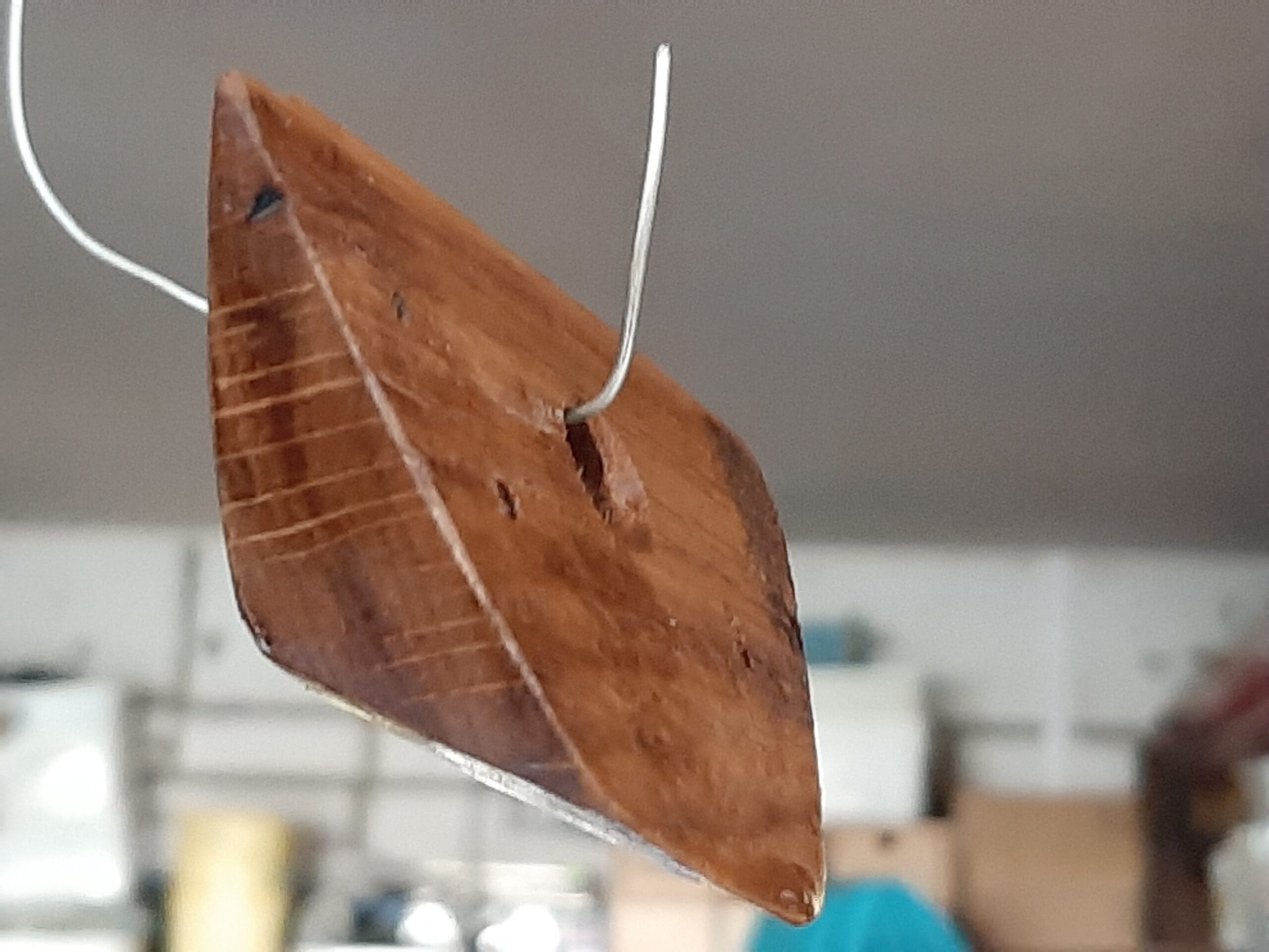 Took quite a long time to get the shape right because I had to be cautious while working with a block that was not much bigger than the light. Shaping and mounting holes all finished and the first coat of varnish done in time for lunch.
I also did a little work on the original compass, finding that the reason for the rattle is that two brass screws were loose inside the case. These are the non-magnetic solution to holding the lead balance weight in place which makes the compass swing on it’s gimbles. The plastic columns (possibly genuine Bakelite being from the 1970s) had broken off with the screws still in place so a little superglue fixed the problem.
Sunday 12th Early start again. Outside and working on the boat for 8:00. First job was to install the compass light now that the two coats of varnish have dried. Much neater than the original and hopefully less impact on night vision in the event that I end up needing to use it. 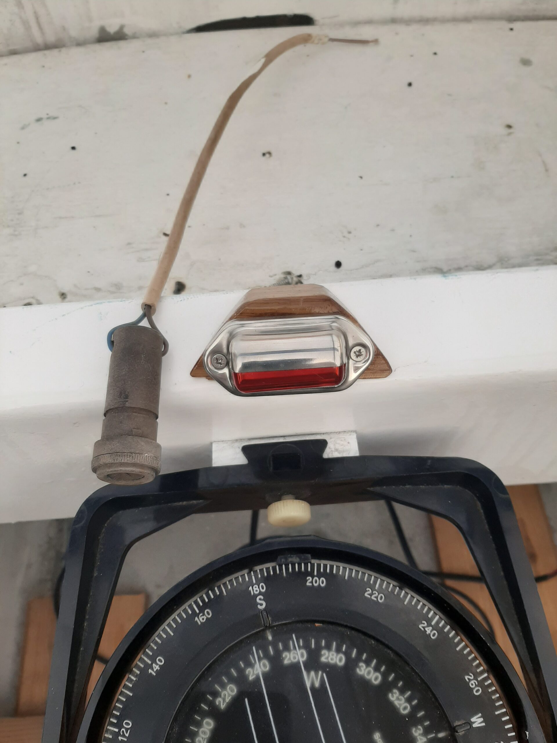 You might wonder why I need a light given that there will usually be phosphors painted on such instruments to give night vision. Well yes it does have all of those but, being presumably at least 45 years old, the only part of the pattern that shows visible emission at night is the open arrow that you rotate to show the intended course. Presumably the radiation in the glass capsules and paint of the other markings has decayed too much to be noticeable when I tested it on a residential street at 11pm a couple of nights ago. Might do better in a true dark night away from even LED street lights, we will see.
As well as the internal lighting I also installed a set of LED navigation lights. Nothing complicated to think about there but I did decide that using low current light sources instead if incandescent bulbs meant I have some ability to throw the saving at having higher output lights. By my thinking more light = more chance of being spotted and avoiding a collision, I therefore opted for the lights designed to be used on boats less than 20 M rather than the less than 12 M version.
Port & starboard lights are attached to the cabin sides in roughly the same place as the original ones. 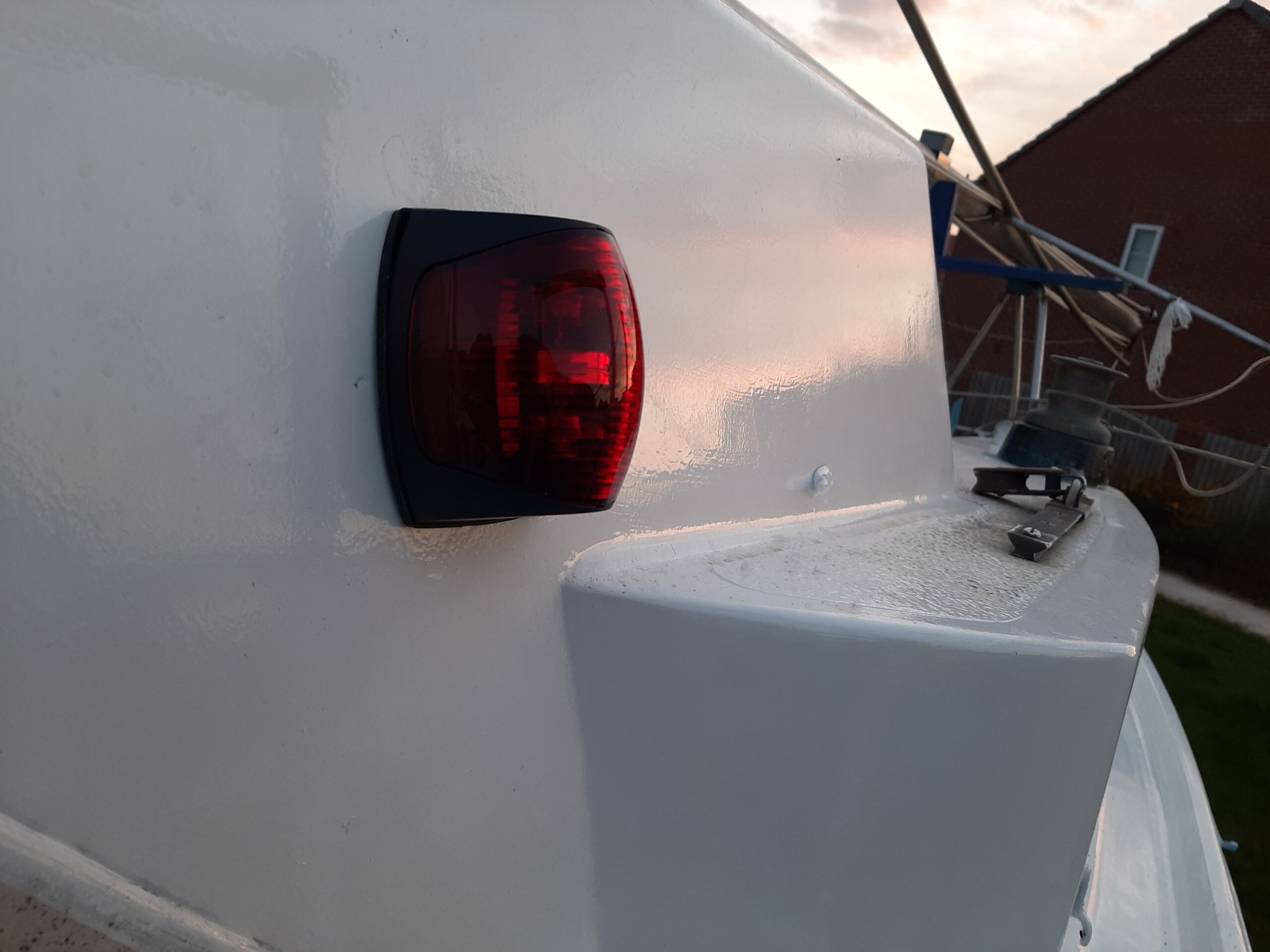 The wires go back to the switch boxes between the headlining and the cabin roof. I had a bit of a trouble with the supplier tough as I initially received 2 port side lights and it took a while to get the exchange done during the COVID shutdown.
The white stern light is mounted on a piece of bent aluminium sheet pop-riveted to the pushpit on the starboard side.  That was originally intended to be a template to cut out a stainless steel version to weld on but then I decided that a couple of coats of the Everbright coating should provide enough protection to have aluminium and stainless steel in apparent contact. I may have to re-do that if there’s much corrosion though.
Not quite a finished job in the photo as I still have to thread the cable into the starboard locker and add a few cable ties.
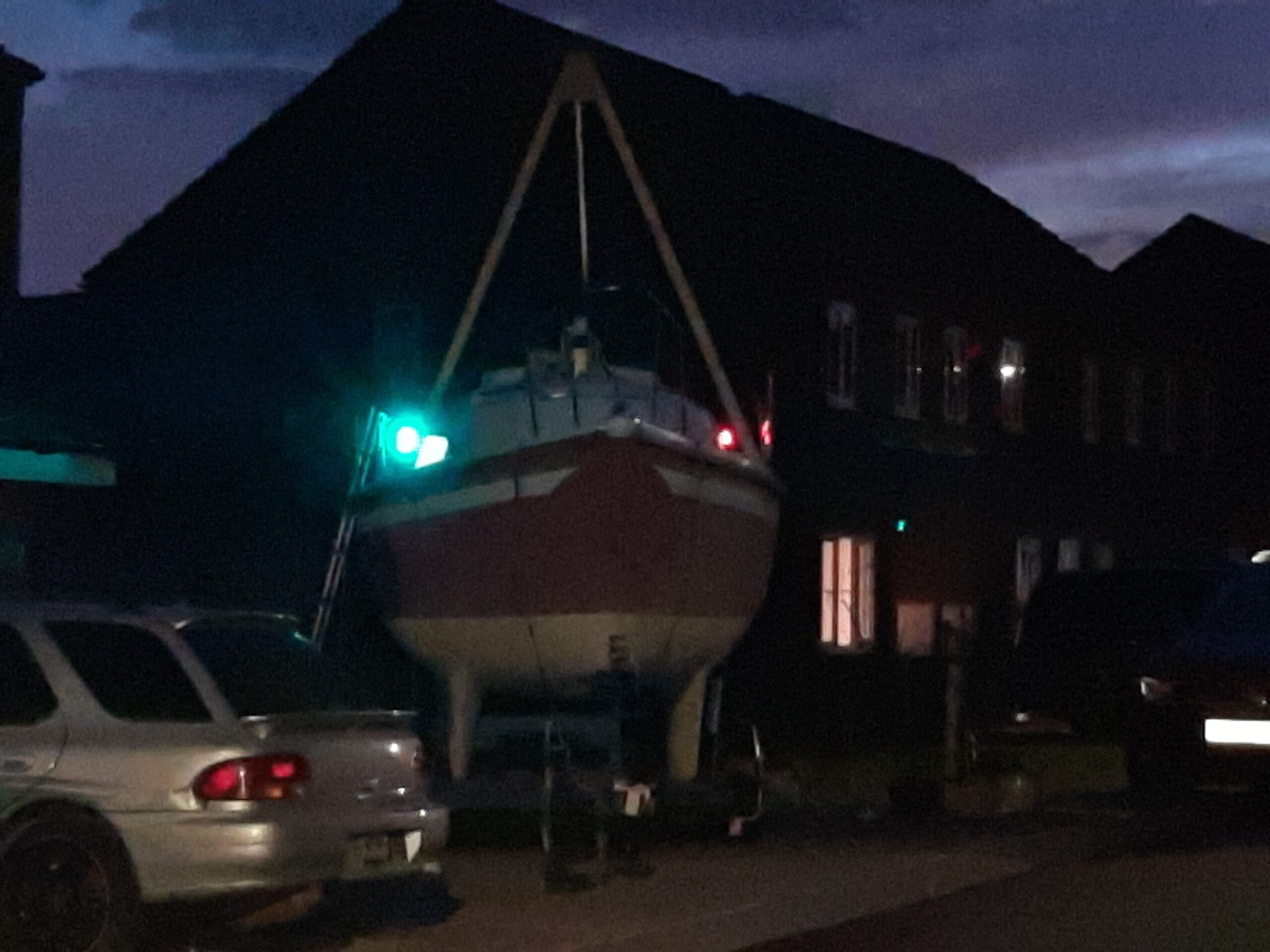
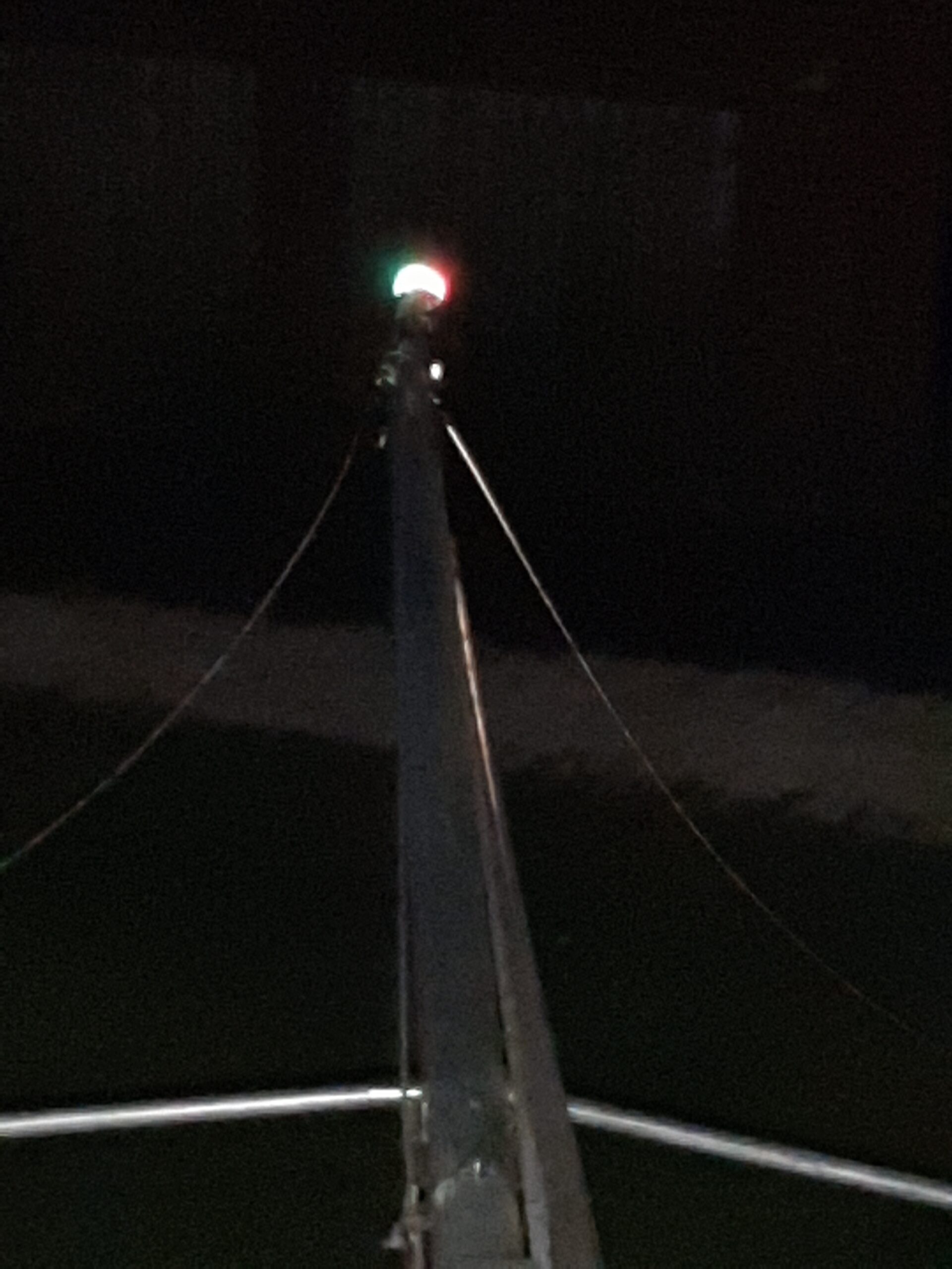
That should be visible enough when I am motoring and the mast head tri-colour light is fairly bright for sailing or at anchor!
Posted 22/10/2020 with a nominal date 17/4/2020 to get the right sequence.